System and method of sub-surface system design and installation

a sub-surface system and system technology, applied in the field of agriculture, can solve the problems of reducing the accuracy of data point locations, adding significant costs, and relying on benchmark and base station locations which can shift, so as to reduce the amount of interface equipment and reduce costs

Inactive Publication Date: 2005-01-13
MEINERS ROBERT E +1
View PDF15 Cites 19 Cited by
  • Summary
  • Abstract
  • Description
  • Claims
  • Application Information

AI Technical Summary

Benefits of technology

[0018] The present invention has been made in view of the above circumstances and has as an aspect to provide a system and method of managing the design and installation of agricultural water management systems. A...

Problems solved by technology

This repeated conversion degrades the precision of the data point locations.
Further, current systems use the highly expensive RTK equipment with the installation machines to try and correct for the error, thus adding significant cost.
Another problem associated with using RTK GPS systems to create topographical maps is dependency on benchmark and base station locations which can shift over time.
The setup of a base station is inconvenient, time consuming, and introduces error into the survey if the exact position cannot be located again.
Thus, locating the base station and benchmarks becomes a serious problem for future use.
Another problem arises from the type of survey equipment required with current systems.
Laser equipment is very costly, increasing both the contractor and farmer's expense.
Yet another problem with present systems and methods is that maps cannot be created in the field either in real time or from a single program.
Instead, current systems address only one function at a time, and do not integrate and stream line the design and build process.
Still another problem with current systems stems from relying on footage measurements.
After maps are created, ...

Method used


Image

  • System and method of sub-surface system design and installation
  • System and method of sub-surface system design and installation
  • System and method of sub-surface system design and installation

Examples


Embodiment Construction

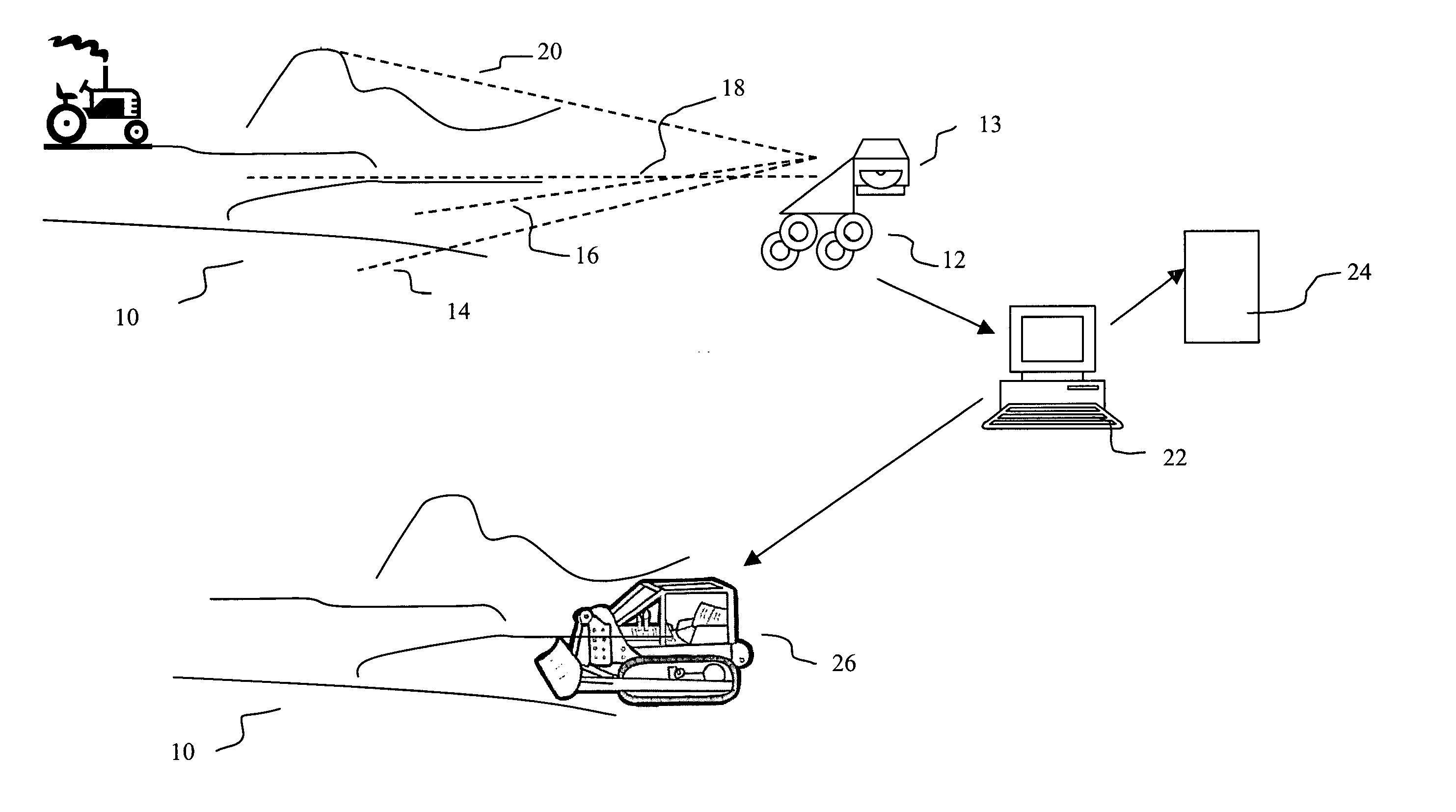
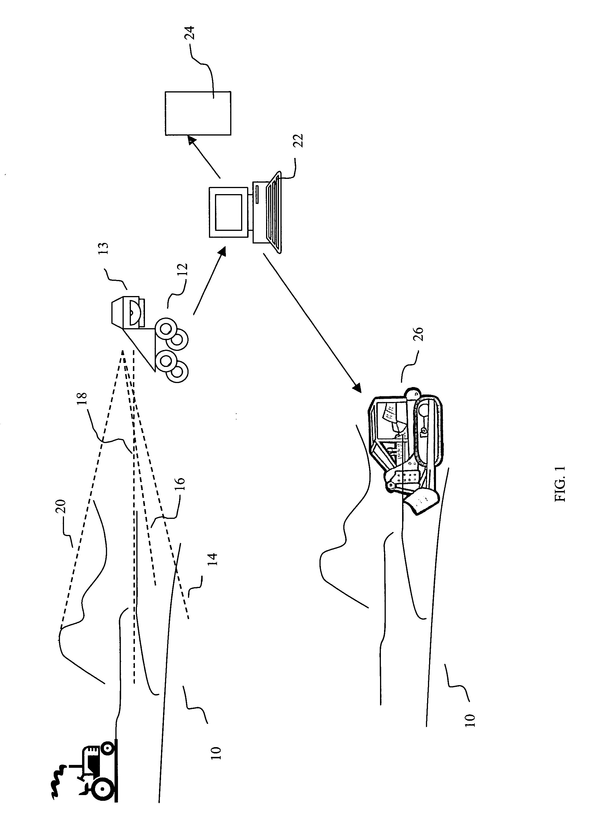
[0026]FIG. 1 illustrates a preferred embodiment of the present invention. An agricultural field 10 requires a drainage system. A mobile vehicle 12 carries an RTK system including a computer having an Input / Output (I / O means) 13 for uploading and downloading data to the RTK system. Preferably the RTK system includes a rugged computer encased to protect the computer from the elements and shock from traveling over the rough terrain. The mobile vehicle may take a variety of forms, such as ATV'S, construction equipment, tractors, trucks, cars, boats, ships, helicopters, airplanes, or the like. A computer having at least a 2.0 Gigahertz processor, a 20 Gigabyte hard drive, and 128 Megabytes of volatile memory is preferred for use with the present invention, although computer having different or less capability may be used as well. The rugged computer stores and executes software for surveying an area using GPS coordinates. The RTK system is used to survey and gather very accurate data poi...


PUM


Abstract

The system and method of the present invention provides comprehensive design and installation management for agricultural water management systems. Maps and grade profiles are created from data collected by Global Positioning devices in the field. Latitude, longitude, and elevation are triangulated from GPS data to develop contour, grade, and profile maps, used to design drainage systems in real time. Customer billing information and vendor pricing information are produced from map and grade profile data. Interfacing and machine control for machines used to install drainage and/or irrigation systems are generated from contour, grade and profile data. Data is exported and imported in common file formats for efficient data exchange.

Description

CROSS-REFERENCE TO RELATED APPLICATIONS [0001] Not applicable. STATEMENT REGARDING FEDERALLY SPONSORED RESEARCH OR DEVELOPMENT [0002] Not applicable. BACKGROUND OF THE INVENTION [0003] 1. Field of the Invention [0004] The present invention relates broadly to the field of agriculture, and more specifically to the use of topographic data in the field of agriculture. [0005] 2. Description of the Related Art [0006] In the field of agriculture, irrigation systems water crop fields, and tile systems are manage water drainage in crop fields. Often, irrigation and tile systems, or agricultural water management systems, are “sub surface,” or installed under ground. Networks of pipe and / or tubing are installed underground for both systems, including main collector lines and a number of outlets. Outlets drain excess water into non-crop areas or drainage ditches which move the water away from crop fields. One or more junction boxes may be installed to check flows, sub mains, and drains. Agricul...

Claims


Application Information

Patent Timeline
IPC IPC(8): A01B79/00A01G25/06G01N1/02G06F17/50
CPCA01B79/005A01G25/06G06Q30/0283G06F17/5004G06F17/5095G01N2001/021G06F30/15G06F30/13
Inventor MEINERS, ROBERT E.MEINERS, CHAD R.
Owner MEINERS ROBERT E
Why Eureka
Try Eureka