Forehead support for facial mask

a technology for facial masks and support points, applied in chemical protection, valves, operating means/releasing devices, etc., can solve the problems of affecting the wearer's nose, affecting the wearer's face, and affecting the wearer's facial mask

Active Publication Date: 2005-02-03
RESMED LTD
View PDF99 Cites 77 Cited by
  • Summary
  • Abstract
  • Description
  • Claims
  • Application Information

AI Technical Summary

Benefits of technology

[0017] Accordingly, in a first aspect, the present invention provides a forehead support adapted to be secured to a respiratory mask, said forehead support including a joining member for securing to the mask and a cushion frame pivotally mounted to the joining member, wh

Problems solved by technology

A problem that arises with existing masks is that with the use of straps, the mask i

Method used


Image

  • Forehead support for facial mask
  • Forehead support for facial mask
  • Forehead support for facial mask

Examples


first embodiment

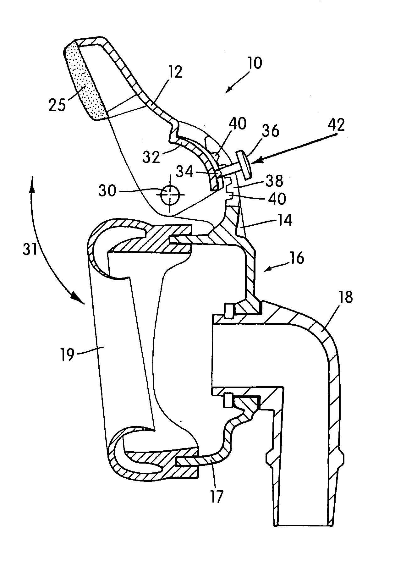
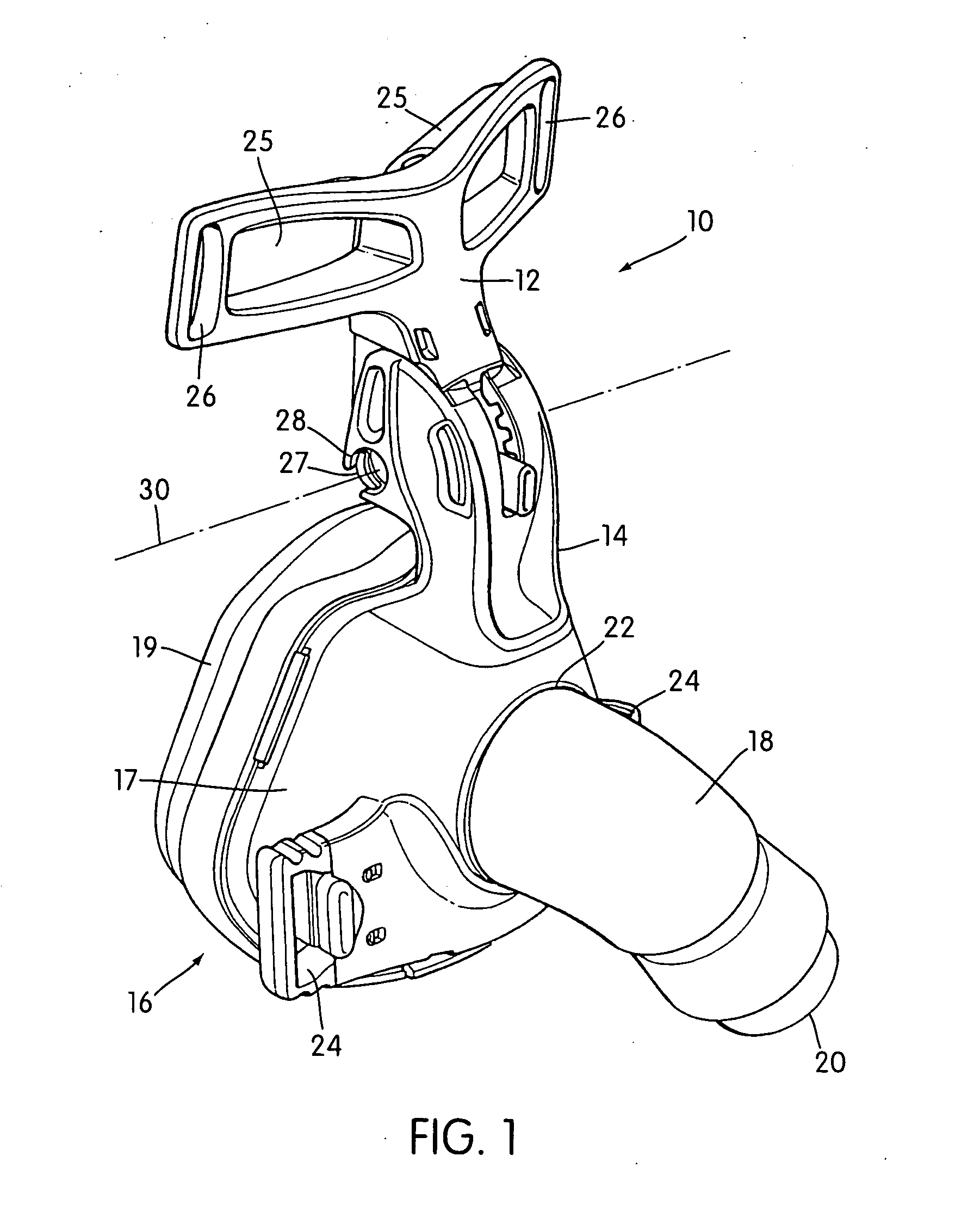
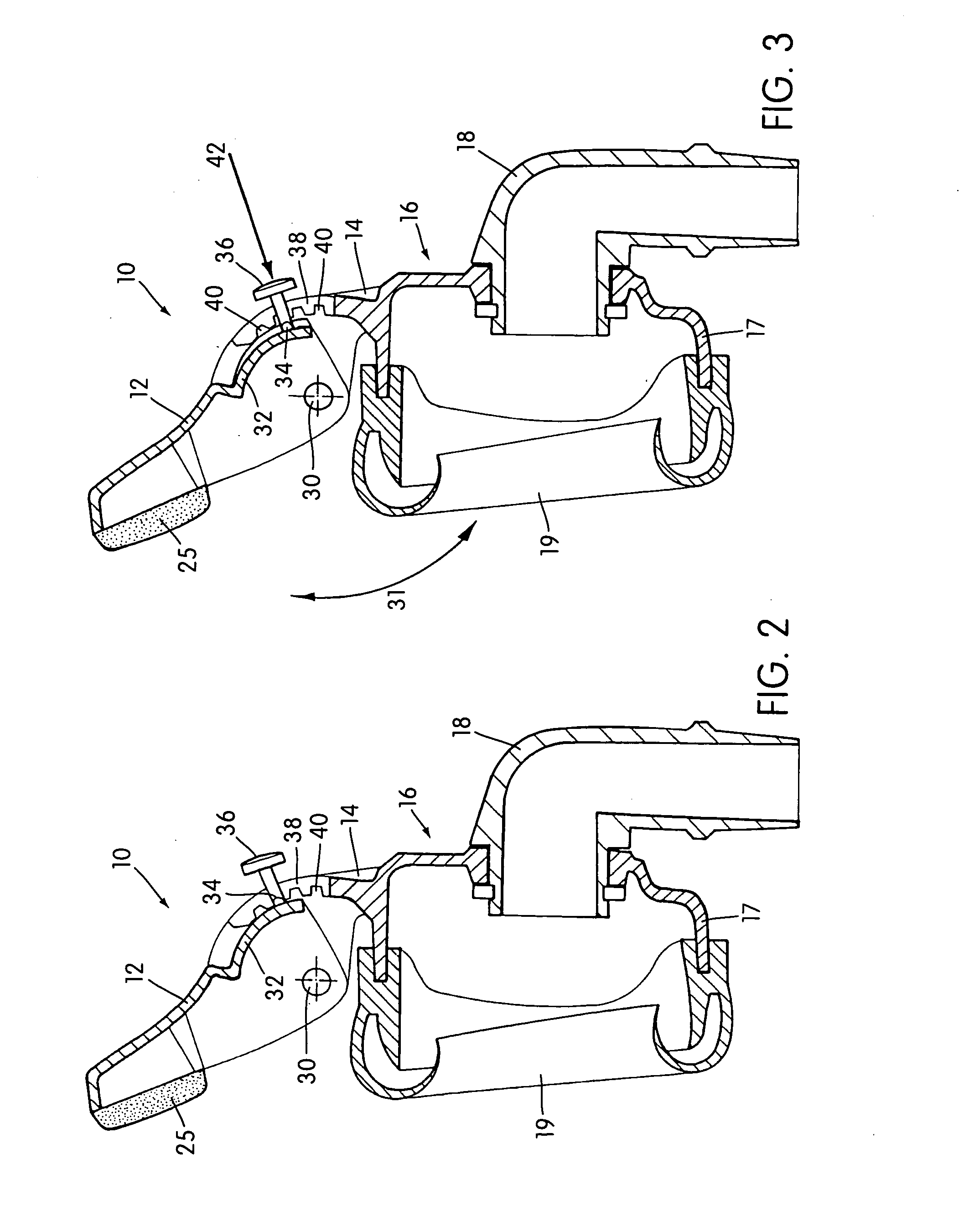
[0108]FIG. 1 shows a forehead support 10 according to the present invention. The forehead support 10 includes a generally T-shaped cushion frame 12 pivotally mounted to a joining member 14. The joining member 14 is connected to a nasal respiratory mask 16 used to supply breathable gas to a wearer's airways, as described in U.S. application Ser. No. 10 / 264,326, currently pending, and U.S. application Ser. No. 09 / 502,745, now U.S. Pat. No. 6,532,961, incorporated by reference in their entireties.

[0109] The mask 16 includes a mask shell 17 and a mask cushion 19. The mask shell 17 also includes an angled connector 18 which has a distal end 20 for connection to a gas supply conduit (not shown) and a proximal end 22 for connection to the mask 16. The connector 18 communicates the supplied gas from the gas supply conduit to the interior of the mask 16. The mask shell 17 also includes a pair of slotted connectors 24 to which are respectively connected ends of a lower head strap (not shown) ...

second embodiment

[0121] In the second embodiment, there are two buttons 36. Pressing the buttons together in the direction of arrows 52 flexes the tongues 34 towards each other to disengage them from the grooves 40 and allow angular adjustment between the cushion frame 12 and the joining member 14. Releasing the buttons 36 allows the tongues 34 to resiliently flex towards, and into engagement with, the grooves 40 to lock the cushion frame 12 and the joining member 14 against relative pivotal movement.

[0122] FIGS. 9 to 14 show a third embodiment of a forehead support 60 according to the present invention. Like reference to those used in describing the first embodiment will also be used to denote like features in relation to the third embodiment.

third embodiment

[0123] In the third embodiment, the cushion frame 12 is integrally molded with the joining member 14 and joined by an integral hinge 62 (sometimes known as a natural or living hinge). The cushion frame 12 and the joining member 14 can be pivoted relative to each other about the hinge 62. The forehead support 60 is molded in a substantially ‘flat’ configuration, as shown in FIG. 9. The cushion frame 12 is then pivoted through approximately 180° relative to the joining member 14 until the tongue 34 engages one of the four grooves 40. As with the earlier embodiments, pressing the button 36 in the direction of arrow 42 frees the tongue 34 from engagement with the grooves to allow adjustment of the angle between the cushion frame 12 and the joining member 14. The button 36 and the tongue 34 are inherently biased to a position engaging one of the grooves 40, again consistent with earlier embodiments.

[0124] In the preferred form shown, the mask shell 17 is also integrally formed with the j...


PUM


Abstract

A respiratory mask assembly includes a frame and a forehead support secured to the frame. The forehead support includes a joining member secured to an upper portion of the frame and a cushion frame movably mounted to the joining member. One of the joining member and cushion frame includes a pair of shafts and the other of the joining member and cushion frame includes a pair of openings. The pair of shafts are respectively received in the pair of openings to couple the cushion frame to the joining member and enable the cushion frame to move relative to the joining member. Each of the shafts has a non-circular cross section defining a major longitudinal axis that is angled forwardly of a vertical axis of one of the joining member and cushion frame so as to angle toward a front portion of one the joining member and cushion frame.

Description

CROSS REFERENCE TO PRIORITY APPLICATION [0001] This application claims the benefit of U.S. Provisional Application No. 60 / 467,570, filed May 5, 2003, incorporated herein by reference in its entirety.FIELD OF THE INVENTION [0002] The present invention relates to a forehead support for a facial mask used to supply breathable gas to a wearer's airways. [0003] The invention has been developed primarily for use in supporting a nasal mask used in Continuous Positive Airway Pressure (CPAP) treatment of, for example, Obstructive Sleep Apnea (OSA) and other ventilatory assistance treatments such as Non-Invasive Positive Pressure Ventilation (NIPPV) and will be described hereinafter with reference to this application. However, it will be appreciated that the invention is not limited to these particular uses and is also suitable for use with, for example, full-face (i.e., nose and mouth) masks. BACKGROUND OF THE INVENTION [0004] CPAP treatment is a common ameliorative treatment for breathing d...

Claims


Application Information

Patent Timeline
IPC IPC(8): A61M16/06A61M16/08
CPCA61M16/06A61M16/0683A61M16/0638A61M16/0616A61M16/0622A61M16/08A61M16/0825A61M16/065
Inventor KWOK, PHILIP R.RAJE, MILIND CHANDRAKANTDAVIDSON, AARON SAMUEL
Owner RESMED LTD
Why Eureka
Try Eureka