Fixed type electrode tip take-out device

a technology of take-out device and electrode tip, which is applied in the direction of welding device, soldering device, manufacturing tool, etc., can solve the problem of irregular position of the upper and lower electrode tips of each group

Active Publication Date: 2005-02-03
OBARA GRP
View PDF5 Cites 20 Cited by
  • Summary
  • Abstract
  • Description
  • Claims
  • Application Information

AI Technical Summary

Benefits of technology

[0003] The invention has been made in view of the problems of the prior art as set forth above, and has an object to provide a fixed type electrode tip take-out device in which boundary walls of respective through holes are formed of elastic walls, and each lowest end portion of the electrode tip of each group is brought into contact with a slide p...

Problems solved by technology

This prior art has the problem in that the electrode tips of each group which are housed in the tip magazine are held down by adding an elastic body which is separately provided so that extra components are needed and positions of the upper and lower electrode tips of each group becom...

Method used


Image

  • Fixed type electrode tip take-out device
  • Fixed type electrode tip take-out device
  • Fixed type electrode tip take-out device

Examples


first example

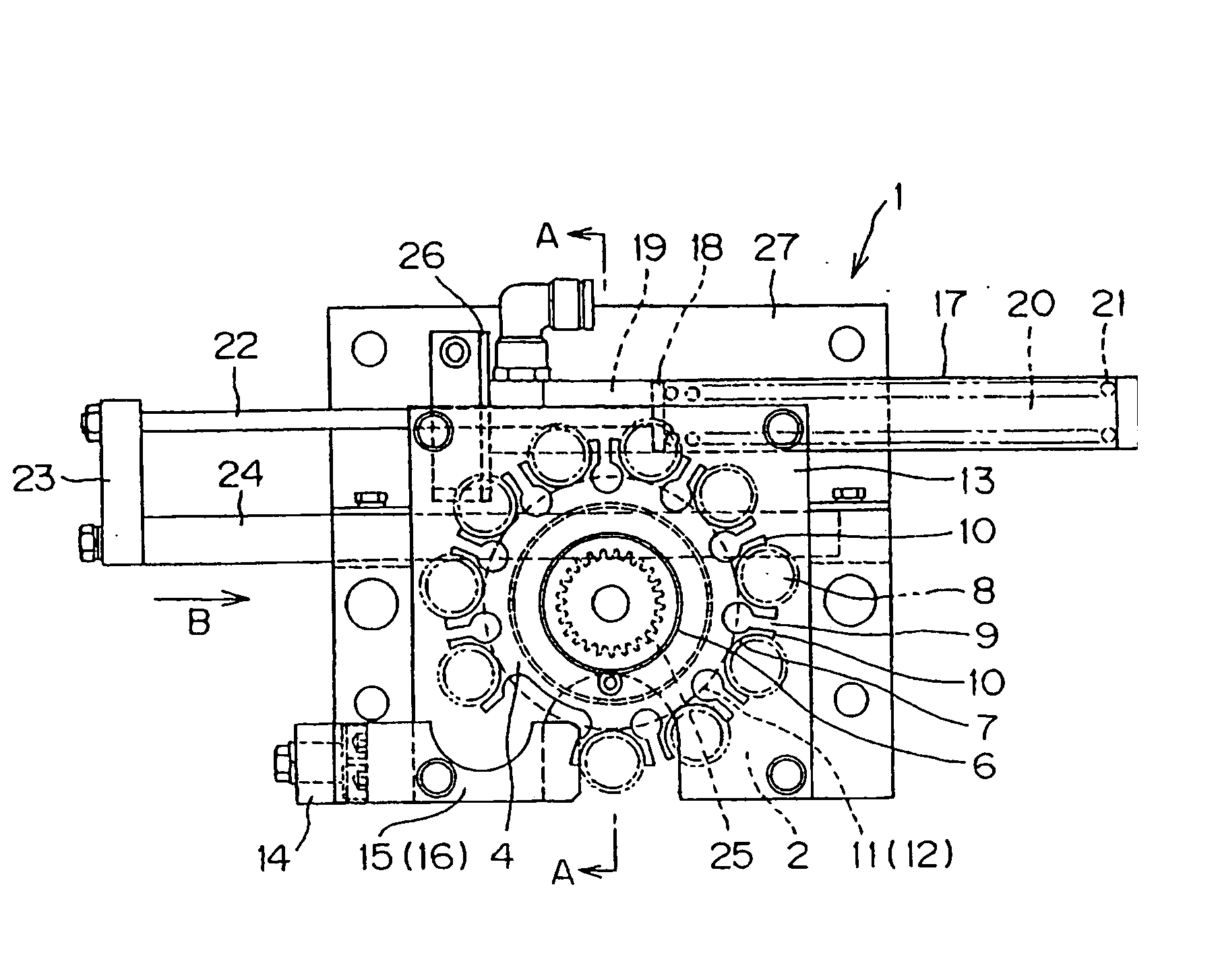
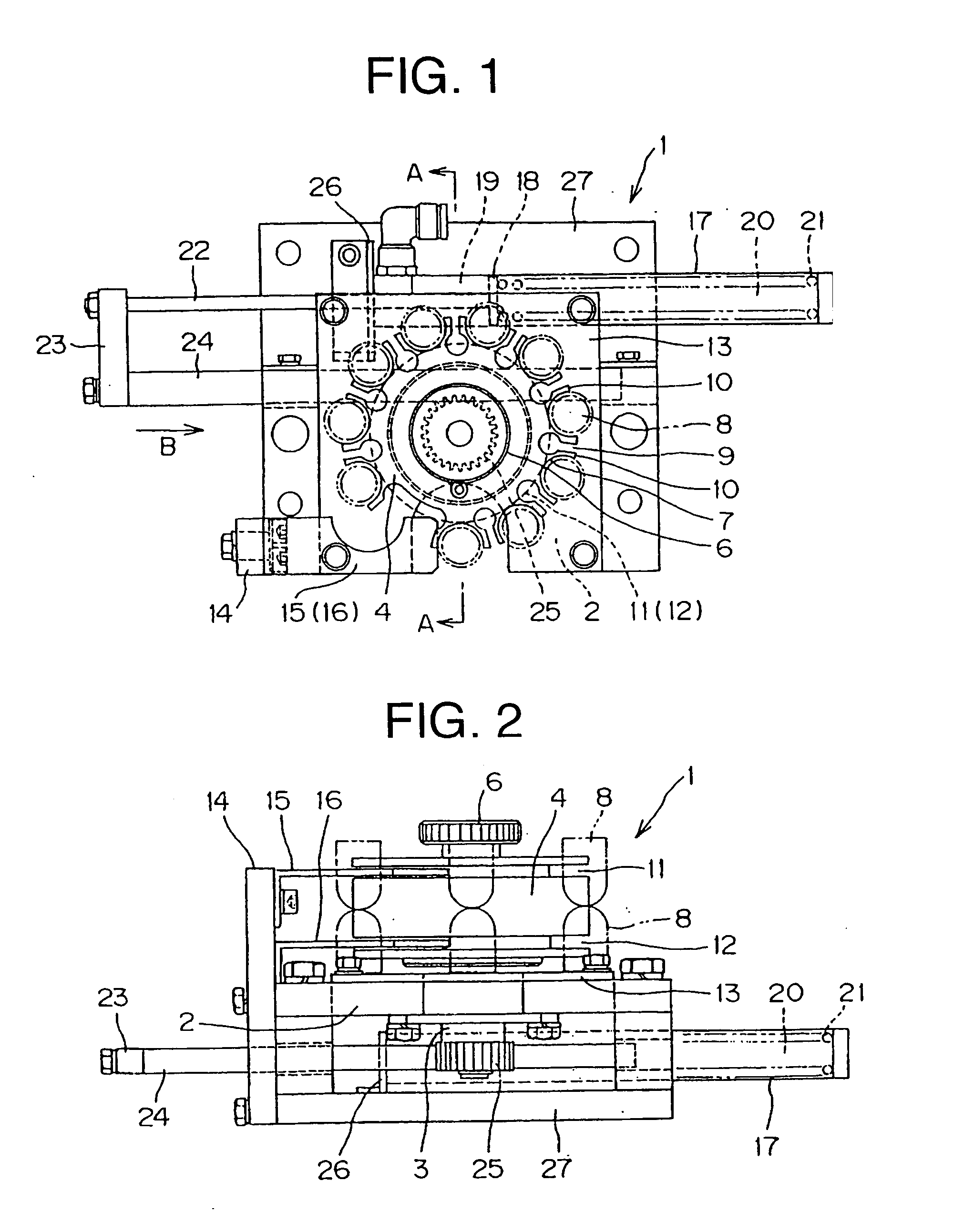
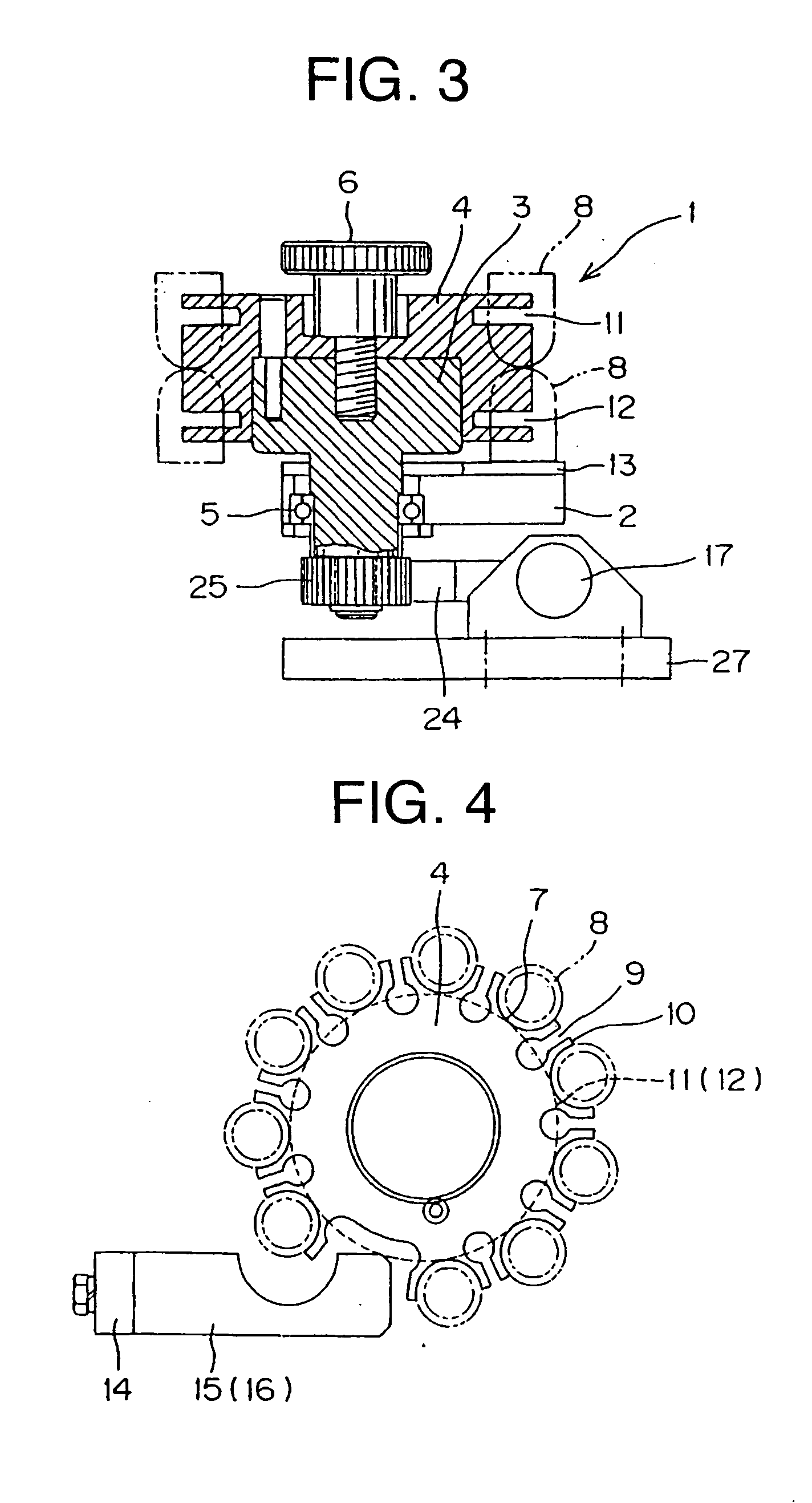
[0020] FIGS. 1 to 4 relate to the fixed type electrode tip take-out device according to the first embodiment of the invention, wherein FIG. 1 is a plan view showing the main portion thereof, FIG. 2 is a front view thereof, FIG. 3 is a sectional view taken along the line A-A shown in FIG. 1, and FIG. 4 is a view for explaining a magazine set position.

[0021] In FIGS. 1 to 4, depicted by 1 is an entire view of the fixed type electrode tip take-out device, wherein a tip magazine 4 is rotatably fixed to a base plate 2 of the fixed type electrode tip take-out device 1 via a rotary shaft 3. Depicted by 5 is a bearing provided between the rotary shaft 3 and the base plate 2, and 6 is a knob provided with a screw part for fixing the tip magazine 4 to the rotary shaft 3 or removing the tip magazine 4 from the rotary shaft 3.

[0022] The tip magazine 4 is substantially discoid and a plurality (e.g. 10 pieces) of semi-cylindrical through holes 7, 7 . . . which are opened at one end and position...

second embodiment

[0033] FIGS. 5 to 9 relate to a fixed type electrode tip take-out device according to the second embodiment of the invention, wherein FIG. 5 is a plan view of the main portion of the fixed type electrode tip take-out device, FIG. 6 is a front view thereof, FIG. 7 is a plan view of a tip magazine, FIG. 8 is a side view of the fixed type electrode tip take-out device shown in FIG. 6, and FIG. 9 is a view for explaining an operation of the fixed type electrode tip take-out device shown in FIG. 5.

[0034] According to the second embodiment, the tip magazine has a substantially rectangular boxed-shape as viewed from the top thereof, and a plurality of semi-cylindrical through holes which are opened at one end and formed to extend from the upper surface to the lower surface of the tip magazine. An urging force of a driving unit relative to the tip magazine operates linearly, which is different from the first embodiment, and other components of the electrode tip take-out device 1 are substa...


PUM


Abstract

There is provided a fixed type electrode tip take-out device capable of solving the problem of irregularities of positions of the upper and lower electrode tips by urging a tip magazine to be movable, and fixing the locations of the electrode tips of each group at the portions to be fixed to a welder, thereby taking out the electrode tips from the tip magazine with accuracy. The tip magazine is urged to be movable relative to a base plate by a driving unit, boundary portions of respective through holes are partitioned by elastic boundary walls in which wedges are inserted in the same direction as an axis of each through hole, and lowest end portions of electrode tips of each group housed in the tip magazine are brought into contact with a slide plate fixed to the base plate, and the upper and lower electrode tips of each group located at portions to be fixed to a welder and positioned by stoppers fixed to the base plate, thereby forming passages of the stoppers on the elastic boundary walls.

Description

FIELD OF THE INVENTION [0001] The invention relates to a device for taking out welding electrode tips engaged in shanks in tapered shape (hereinafter referred to as taper-engaged) from a tip magazine. BACKGROUND OF THE INVENTION [0002] There is a fixed type electrode tip take-out device for taking out welding electrode tips taper-engaged in shanks from a tip magazine, which is, for example, disclosed in Japanese Utility Model Laid Open Publication No. 5-28575, wherein a plurality of semi-cylindrical through holes are opened at one end and positioned adjacent to each other around the tip magazine, and two electrode tips are grouped and housed up and down oppositely in each through hole. This prior art has the problem in that the electrode tips of each group which are housed in the tip magazine are held down by adding an elastic body which is separately provided so that extra components are needed and positions of the upper and lower electrode tips of each group becomes irregular. Fur...

Claims


Application Information

Patent Timeline
IPC IPC(8): B23K11/36B23K11/30B23K11/31
CPCB23K11/3072B23K11/30B23K11/36B23K37/00B23P19/04
Inventor IZUMI, TAKEHIROKANNO, TAKASHIHAYAFUJI, KENJI
Owner OBARA GRP
Why Eureka
Try Eureka