Test tube cap removing apparatus

Active Publication Date: 2005-03-03
IDS CO LTD
View PDF2 Cites 37 Cited by
  • Summary
  • Abstract
  • Description
  • Claims
  • Application Information

AI Technical Summary

Problems solved by technology

However, with the test tube cap removing apparatus of Document 1, if the size of the test tube or the type of the cap is changed, it is difficult to rem

Method used


Image

  • Test tube cap removing apparatus
  • Test tube cap removing apparatus
  • Test tube cap removing apparatus

Examples


Embodiment Construction

[0020] An embodiment of the present invention will now be described with reference to the accompanying drawings.

[0021] A test tube cap removing apparatus according to the embodiment, which is descried below, is capable of quickly and exactly removing a cap from a test tube even where test tubes of various sizes are used and various types of caps are attached to opening portions of test tubes.

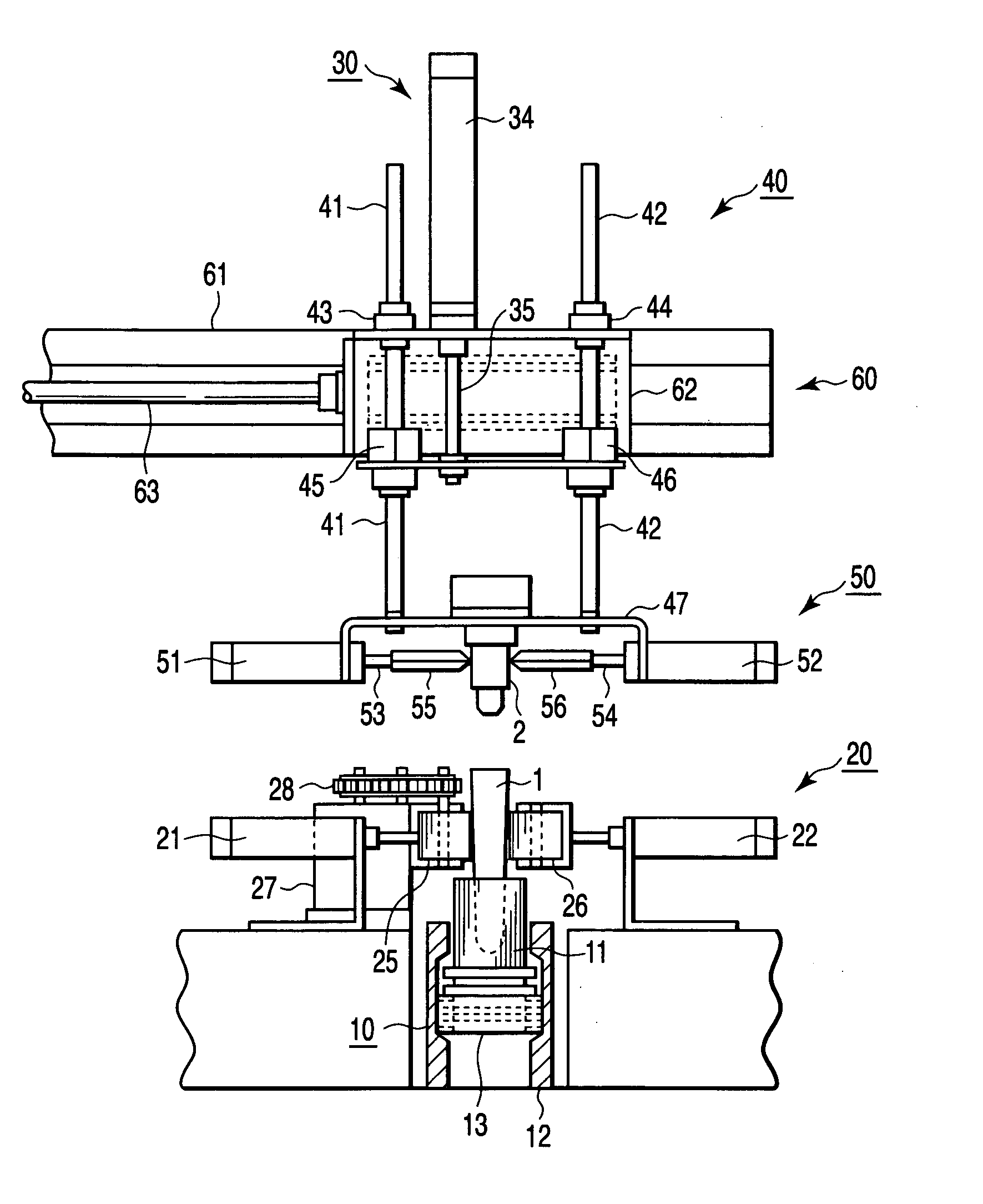
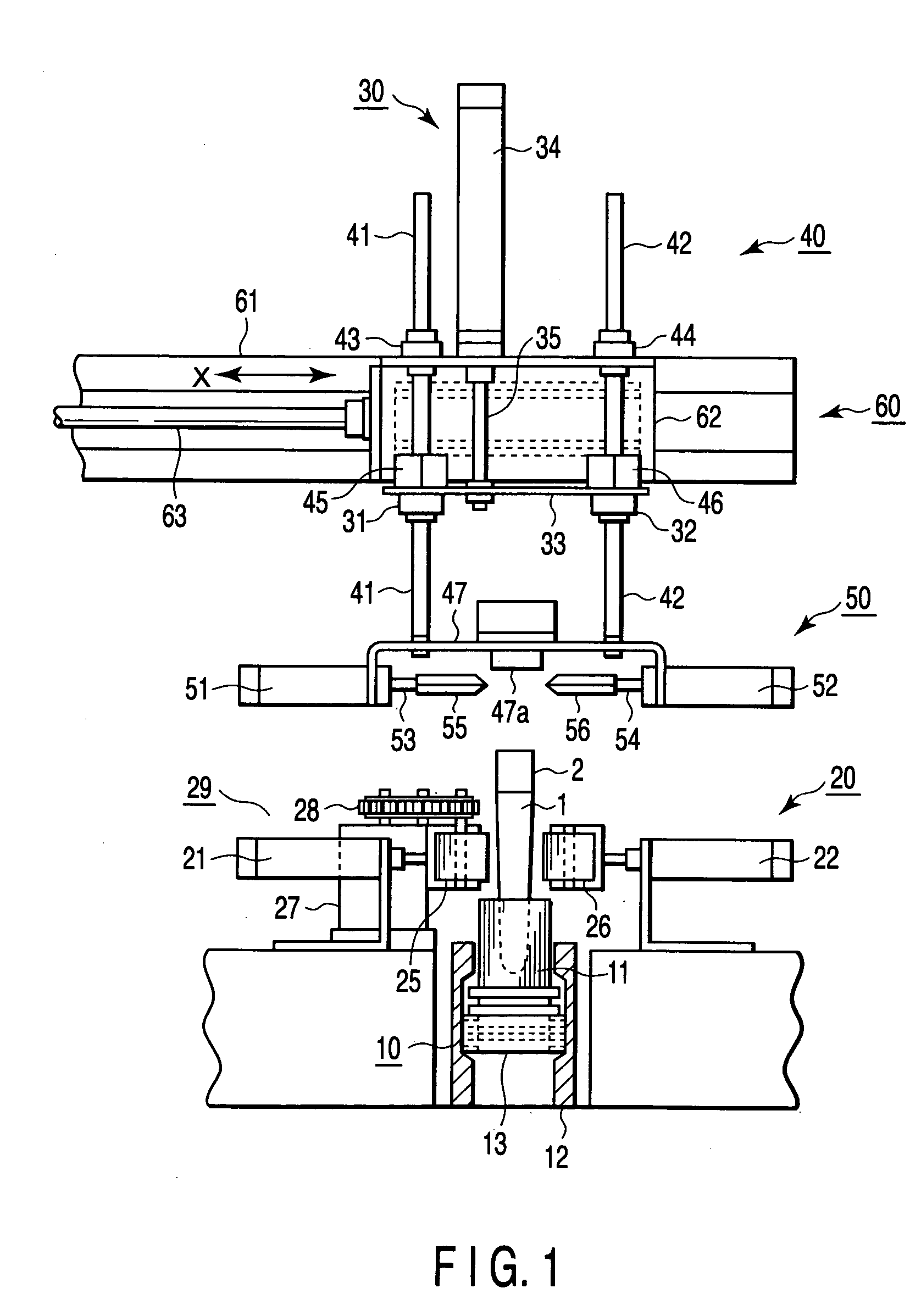
[0022]FIG. 1 is a front view of an example of the test tube cap removing apparatus according to the embodiment of the present invention. FIG. 1 shows a first operation state of the apparatus.

[0023] A convey mechanism 10, which is provided below the test tube cap removing apparatus, conveys a test tube 1 with an opening closed by a cap 2, to a predetermined position where a cap removing operation is to be performed.

[0024] The convey mechanism 10 conveys a holder 11, which can hold the test tube 1 in a vertical state, to a predetermined position by means of a convey lane that comprises a guide...


PUM


Abstract

In an embodiment of the invention, a test tube cap removing apparatus includes a fixing unit that holds a test tube having an opening portion that is closed by a cap, a hold unit that is situated above the cap in an axial direction of the test tube, has a position that is variable relative to the test tube in the axial direction, and is capable of contacting a top portion of the cap, and a clamp unit that is provided on the hold unit, supports the cap at side surfaces of the cap in a case where the hold unit is put in contact with the top portion of the cap, and removes the cap from the test tube in a case where the hold unit moves upwards relative to the test tube in the axial direction.

Description

CROSS-REFERENCE TO RELATED APPLICATIONS [0001] This application is based upon and claims the benefit of priority from prior Japanese Patent Application No. 2003-306492, filed Aug. 29, 2003, the entire contents of which are incorporated herein by reference. BACKGROUND OF THE INVENTION [0002] 1. Field of the Invention [0003] The present invention relates to a test tube cap removing apparatus for automatically removing a cap that is attached to an opening portion of a test tube in which a specimen is to be contained. [0004] 2. Description of the Related Art [0005] In a conventional test tube cap removing apparatus, a cap that closes the opening of a test tube is clamped by distal end portions of cap-removing arms in the state in which the test tube is clamped by a test tube clamper. In this apparatus, the cap-removing arms are pulled up by a cap-removing-arm drive cylinder, thereby automatically removing the cap. [0006] Document 1 (Jpn. Pat. Appln. KOKAI Publication No. 5-228379) discl...

Claims


Application Information

Patent Timeline
IPC IPC(8): G01N35/02B01L3/14B01L9/06B67B7/06G01N35/00
CPCB01L3/50825G01N2035/0405G01N2035/00287G01N35/0099
Inventor ITOH, TERUAKI
Owner IDS CO LTD
Why Eureka
Try Eureka