Method and apparatus for fatigue testing

Active Publication Date: 2005-03-10
NHK SPRING CO LTD
View PDF13 Cites 16 Cited by
  • Summary
  • Abstract
  • Description
  • Claims
  • Application Information

AI Technical Summary

Benefits of technology

[0010] The invention solves the problems and overcomes the drawbacks and deficiencies of conventional fatigue test system designs by pr

Problems solved by technology

Accordingly, the number of springs which may be tested in a conventional fatigue test system at any given time is limited primarily by the driving capacity of the system.
While the mechanism disclosed in the '241 patent enables testing of multiple springs, it is nevertheless limited to compression as opposed to compression/tension testing of multiple springs.
Moreover, due to the requirement for adjustment of numerous levers and guides, in operation, the mechanism disclosed in the '241 patent is completely impractical for high speed and repeatable spring testing, as is required in today's automotive and other mass manufacturing environments.
As discussed above for the mechanism of the '241 patent, although the device of SAE '

Method used


Image

  • Method and apparatus for fatigue testing
  • Method and apparatus for fatigue testing
  • Method and apparatus for fatigue testing

Examples


Example

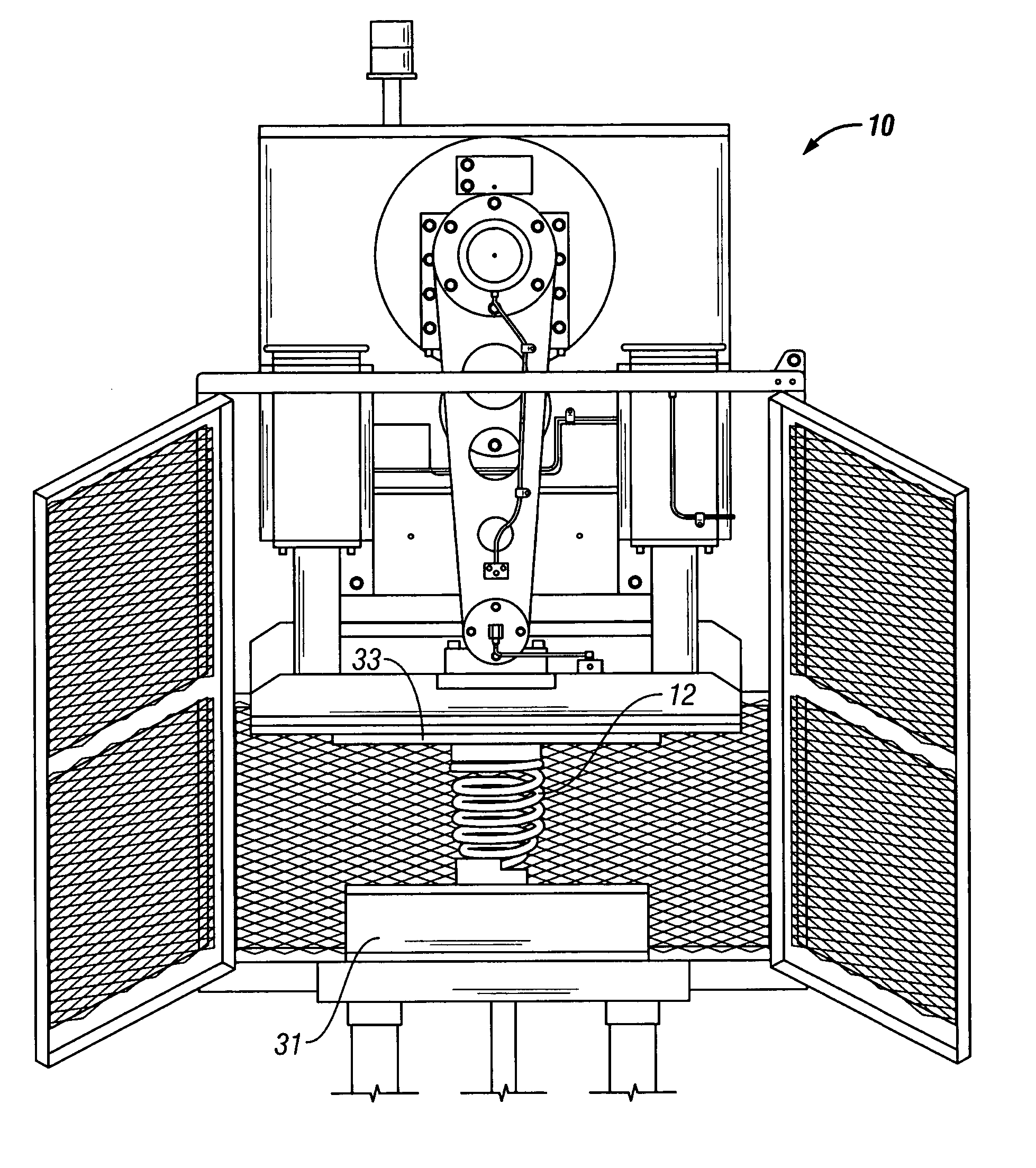
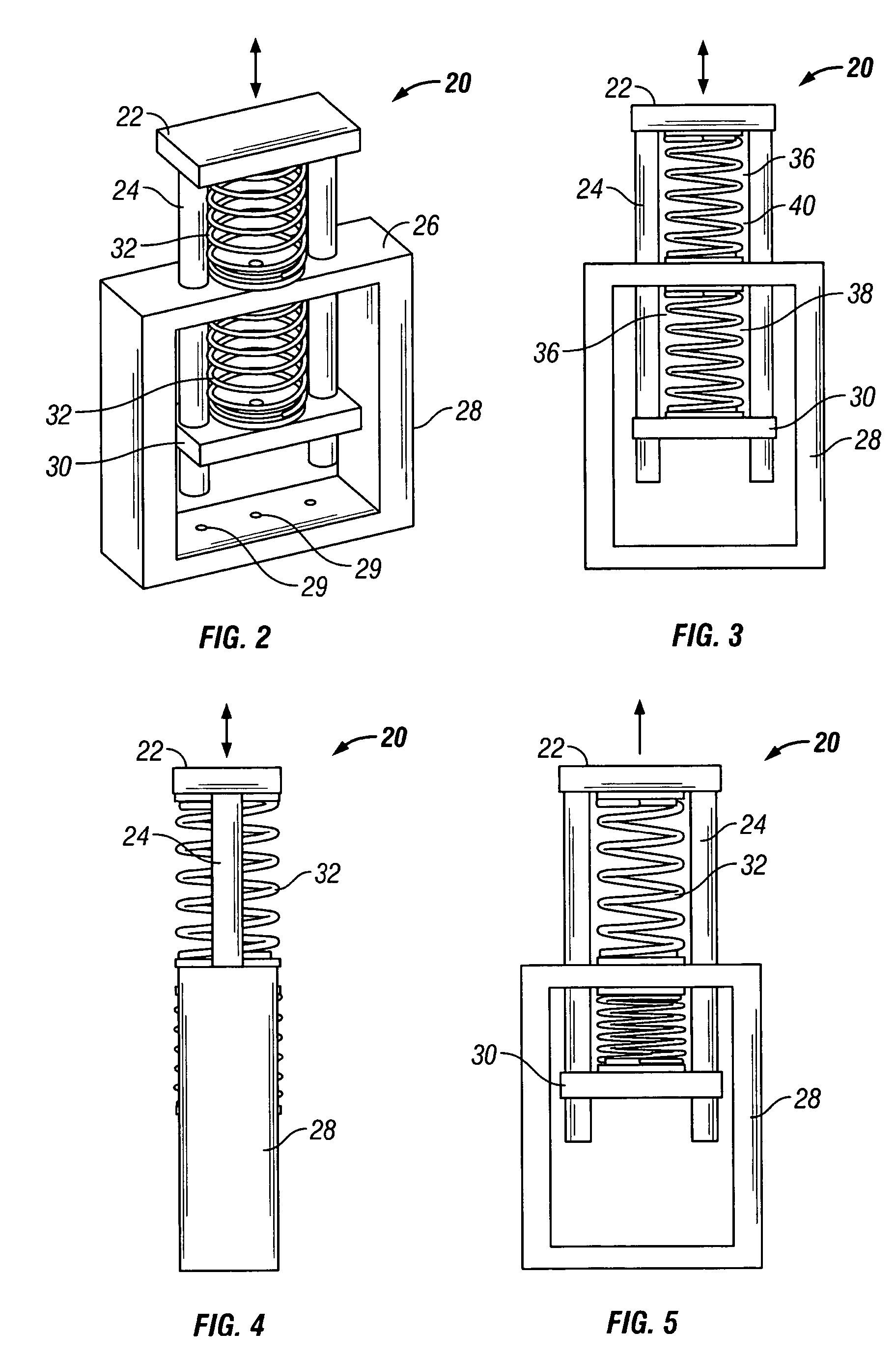
[0039] Specifically, as illustrated in FIGS. 2-5, the first embodiment of system 20 may include an upper plate 22 fixedly connectable to a driving mechanism, such as mechanism 10 illustrated in FIG. 1, of a conventional fatigue test system, such as at 33. System 20 may include at least two extensions, illustrated as circular shafts 24 in FIG. 2, disposed within suitable openings (not shown) in top wall 26 of frame 28. The openings in top wall 26 may include suitable bearings (not shown) for permitting smooth reciprocation of shafts 24 therein. It should be noted that shafts 24 may be formed of a variety of cross-sections for permitting reciprocation of plates 22, 30 therewith. Frame 28 may include a plurality of fixing points 29 for fixing frame 28 to reaction mass 31 (see FIG. 1). Shafts 24 may be fixedly mounted to lower plate 30 at or adjacent their bottom-most ends thereof. Lower plate 30 may include a retention means such as a pin (not shown), ball-screw locking mechanism (not ...

Example

[0042] The second embodiment of system 100 will now be described in detail in reference to FIGS. 6-8.

[0043] Specifically, for the second embodiment of system 100, as illustrated in FIGS. 6-8, system 100 may include a vertically fixable plate 42 connectable to a driving mechanism 10 of a conventional fatigue test system, such as the system disclosed in FIG. 1. System 100 may include shafts 44 disposed within suitable openings in plate 42 and movable plate 46. Shafts 44 may be fixedly mounted to lower fixing plate 48. As discussed above for the first embodiment of system 20, for the second embodiment of system 100, it should be noted that shafts 44 may be formed of a variety of cross-sections for permitting reciprocation of plate 46 by means of driving mechanism 10. Plate 42 may include a retention means such as a pin (not shown), ball-screw locking mechanism (not shown) or suitable fastening means disposed on a threaded section thereof for permitting vertical adjustability and reten...

Example

[0046] The third embodiment of system 200 will now be described in detail in reference to FIGS. 9-11.

[0047] Specifically, for the third embodiment of system 200, as illustrated in FIGS. 9-11, system 200 may include plates 62 slidably disposed on shafts 68, and a driving mechanism 64, such as a driving mechanism of a MTS actuator, having a piston (not shown) including piston rods 66. Shafts 68 may be disposed within suitable openings in plates 62, in a similar manner as shafts 44 of the second embodiment of system 100. As discussed above for the first and second embodiments of systems 20, 100, for the third embodiment of system 200, it should be noted that shafts 68 may be formed of a variety of cross-sections for permitting sliding movement of plates 62 for insertion of springs 70. Plates 62 may each include a retention means such as a pin (not shown), ball-screw locking mechanism (not shown) or suitable fastening means disposed on a threaded section thereof for permitting sliding ...


PUM


Abstract

A fatigue test system includes a frame having top, intermediate and bottom supports each operatively interconnected by at least one extension, and the intermediate support being disposed between the top and bottom supports. The fatigue test system further includes a driving mechanism connectable to one of the supports to drive the support substantially along a longitudinal axis of the extension for fatigue testing at least one spring disposed between the top and intermediate supports, and at least one further spring disposed between the intermediate and bottom supports. In an alternative embodiment, the fatigue test system includes a frame including top and bottom supports each interconnected by an extension, and a driving mechanism disposed between the top and bottom supports for driving springs against the top and bottom supports, each spring being fatigue tested by being driven along a longitudinal axis of the extension or a central axis of the spring.

Description

RELATED APPLICATIONS [0001] This application claims benefit of priority of Provisional Application Ser. No. 60 / 500,266 filed on Sep. 5, 2003.BACKGROUND OF INVENTION [0002] a. Field of Invention [0003] The invention relates generally to fatigue testing, and more particularly to a method and apparatus for fatigue testing springs and other such devices. [0004] b. Description of Related Art [0005] Single story coil fatigue test systems are generally used in the art to fatigue test coil springs and other such devices. As disclosed in JP 410260122A, and further in U.S. Pat. No. 2,350,722, the disclosure of which is incorporated herein by reference, conventional spring fatigue test systems generally include a fatigue testing machine similar to the one disclosed in FIG. 1 herein. Referring to FIG. 1, conventional fatigue testing machines generally include a mechanism 10 driven into one or more mounted coil springs 12 repeatedly using hydraulic, electrical or pneumatic power until the spring...

Claims


Application Information

Patent Timeline
IPC IPC(8): G01N3/00G01N3/04G01N3/32
CPCG01N3/00G01N3/32G01N2203/0464G01N2203/0073G01N2203/0292G01N2203/0016
Inventor SHELBY, RYAN
Owner NHK SPRING CO LTD
Why Eureka
Try Eureka