Apparatus for carrying golf clubs

Inactive Publication Date: 2005-03-24
CHENTERLON
View PDF7 Cites 6 Cited by
  • Summary
  • Abstract
  • Description
  • Claims
  • Application Information

AI Technical Summary

Benefits of technology

[0005] It is an objective of the present invention to provide a club-carrying that is aesthetically pleasing.
[0006] It is another objective of the present invention to provide a club-carrying apparatus that can stand stably.

Problems solved by technology

The rods however provide inadequate limit because of its inadequate rigidity.
However, the cutouts are often not neatly cut and therefore not aesthetically pleasing.

Method used


Image

  • Apparatus for carrying golf clubs
  • Apparatus for carrying golf clubs
  • Apparatus for carrying golf clubs

Examples


Embodiment Construction

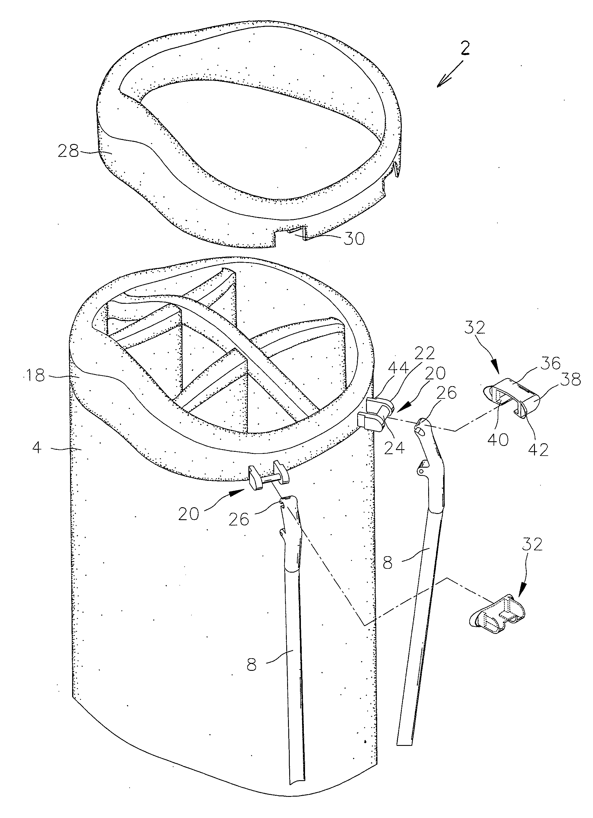
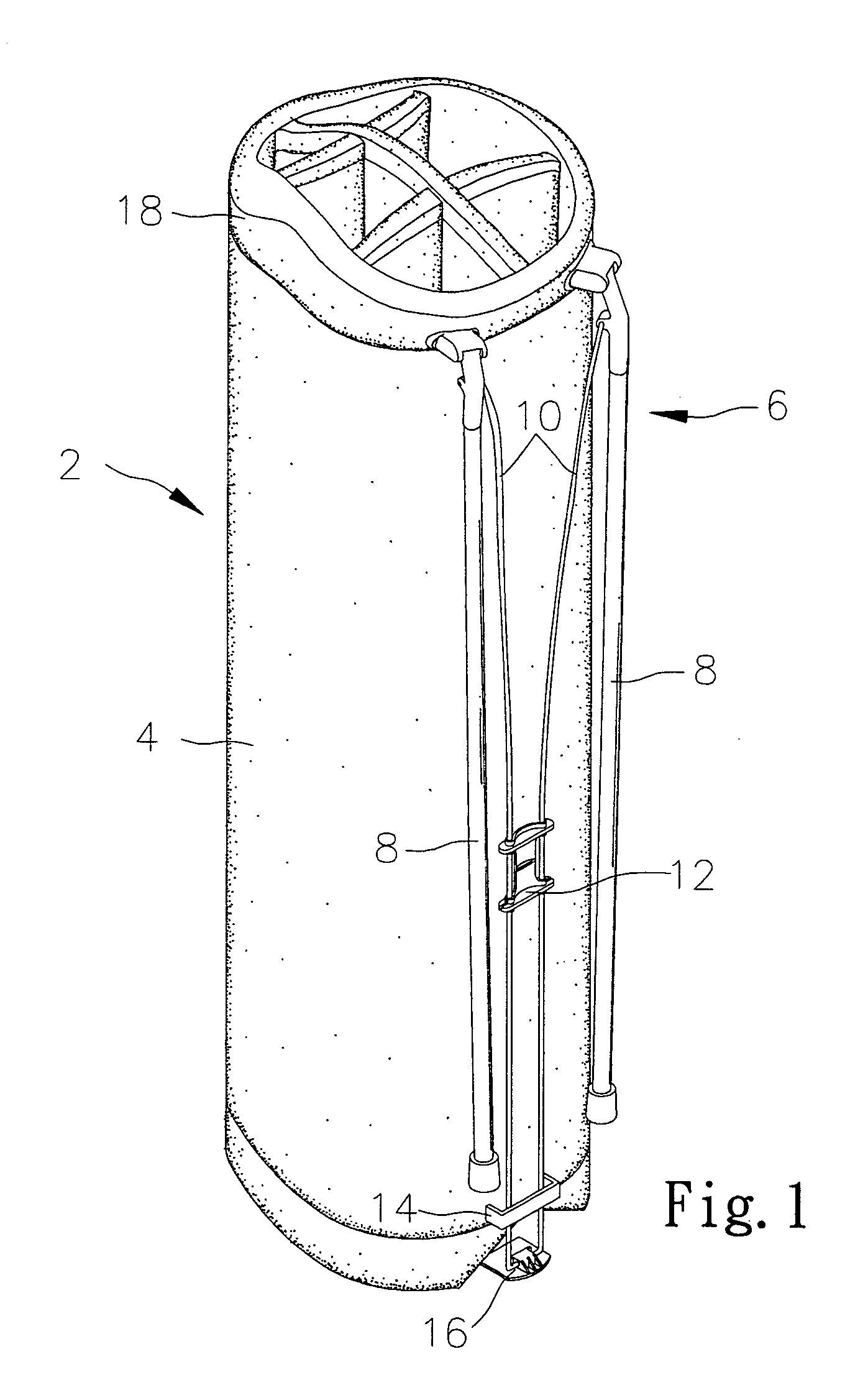
[0015] Referring to FIGS. 1 and 2, according to the preferred embodiment of the present invention, a club-carrying apparatus 2 includes a bag 4 and a support device 6 for helping the bag 4 stand.

[0016] The support device 6 includes two legs 8, two rods 10, a first restraint 12, a second restraint 14 and a foot 16. The legs 8 are pivotally connected with the bag 4. An upper end of each rod 10 is attached to one leg 8. The rods 10 are held in position relative to each other by means of the first restraint 12. The second restraint 14 is attached to the bag 4. The rods 10 are bent so that their lower ends can be inserted through the second restraint 14. Then, the lower end of each rod 10 is attached to the foot 16.

[0017] In use, the legs 8 are pivoted from the bag 4. The upper ends of the rods 10 are moved from the bag 4 because of the pivotal of the legs 8. The second restraint 14 keeps the lower ends of the rods 10 close to the bag 4. Thus, the rods 10 limit the pivotal of the legs ...


PUM


Abstract

A club-carrying apparatus includes a bag, a frame attached to an upper edge of the bag, two lugs formed on the frame, two legs pivotally connected with the lugs, a piece of cloth concealing the frame and defining two cutouts encompassing the lugs, and two shields concealing the lugs and the cutouts.

Description

FIELD OF INVENTION [0001] The present invention relates to a club-carrying apparatus. BACKGROUND OF INVENTION [0002] A conventional club-carrying apparatus includes a bag and a support device for help the bag stand. The support device includes two legs, two rods, a first restraint, a second restraint and a foot. The legs are pivotally connected with the bag. An upper end of each rod is attached to one leg. The rods are held in position relative to each other by means of the first restraint. The second restraint is attached to the bag. The rods are bent so that their lower ends can be inserted through the second restraint. The lower end of each rod is attached to the foot. In use, the legs are pivoted from the bag. The upper ends of the rods are moved from the bag because of the pivotal of the legs. The second restraint keeps the lower ends of the rods close to the bag. Thus, the rods limit the pivotal of the legs within a proper range. The rods however provide inadequate limit becau...

Claims


Application Information

Patent Timeline
IPC IPC(8): A63B55/04
CPCA63B55/04A63B55/57A63B55/50
Inventor CHEN, CHANGFU
Owner CHENTERLON
Why Eureka
Try Eureka