Fish tape handle with retention feature

a technology of tape handle and fish, which is applied in the direction of cables, take-up reel/drum arrangements, cables laying apparatus, etc., can solve the problems of tape “springing out” of the case or the handle, unintentional separation of the case, and unfavorable users, etc., to achieve the effect of improving the handle design

Active Publication Date: 2005-03-24
IDEAL IND INC
View PDF24 Cites 3 Cited by
  • Summary
  • Abstract
  • Description
  • Claims
  • Application Information

AI Technical Summary

Benefits of technology

[0006] The present invention is a fish tape housing having a handle grip and a generally annular case. The case has two halves each including a radial wall and inner and outer axial half walls. The ends of the axial half walls are in facing relation. The outer axial half walls define a slot between them. Screws hold the case halves together. Together the radial walls and axial half walls define a fish tape receiving chamber. A handle grip has a central portion and two legs which are connected by an arcuate shoe. The shoe rides on the exterior surface of the outer half walls. A web on the underside of the shoe extends through the slot to the interior of the case. A continuous hoop or belt is attached to the web. The belt has a outside diameter slightly less than the inside diameter of the outer half walls. The continuous belt allows users of fish tapes to employ the device without fear of the tape escaping the confines of the housing, should the annular walls separate. The belt constrains the tape within the chamber, even under extreme conditions such as the fish tape being dropped from the top of a ladder, or the like.
[0007] In addition, the fish tape housing of the present invention provides an improved handle design. The handle has a passageway defined by top and bottom walls and first and second posts. The passageway has a throat adapted to receive the tape therein. The throat defines a longitudinal axis. The first post is disposed laterally of the longitudinal axis on a first side while the second post is disposed laterally of the longitudinal axis on a second side. Thus, the first and second posts are laterally spaced from one another such that a tape in the passage-way is restrained on both sides and cannot pop out of the passageway. The first and second posts are also longitudinally spaced from one another to define a laterally-directed port. Installation of the tape in the case is achieved by passing an end portion of the tape through the port and then rotating the coil of tape ninety degrees to place the coil into an open case half. This construction obviates the need to thread the entire tape through the handle passageway.

Problems solved by technology

However, the natural resilience of the material makes the coil unruly.
Traditional housing and handle members present a number of problems.
However, the case halves may also unintentionally separate when dropped or under otherwise subjected to extreme conditions.
The possibility of the tape “springing out” of the case or handle presents a danger to users, particularly where the tape is of a material such as steel.
The tape is particularly prone to popping out of its slot in the handle because the slot is fully open on one side of the handle.

Method used


Image

  • Fish tape handle with retention feature
  • Fish tape handle with retention feature
  • Fish tape handle with retention feature

Examples


Embodiment Construction

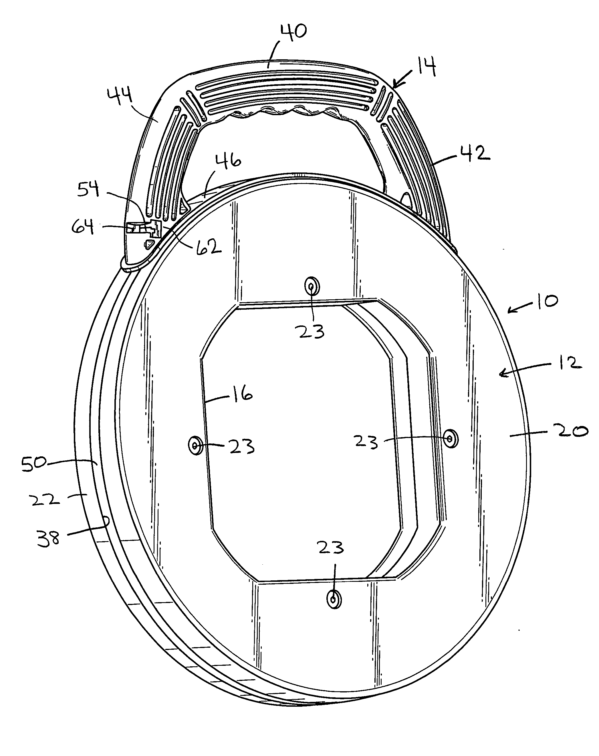
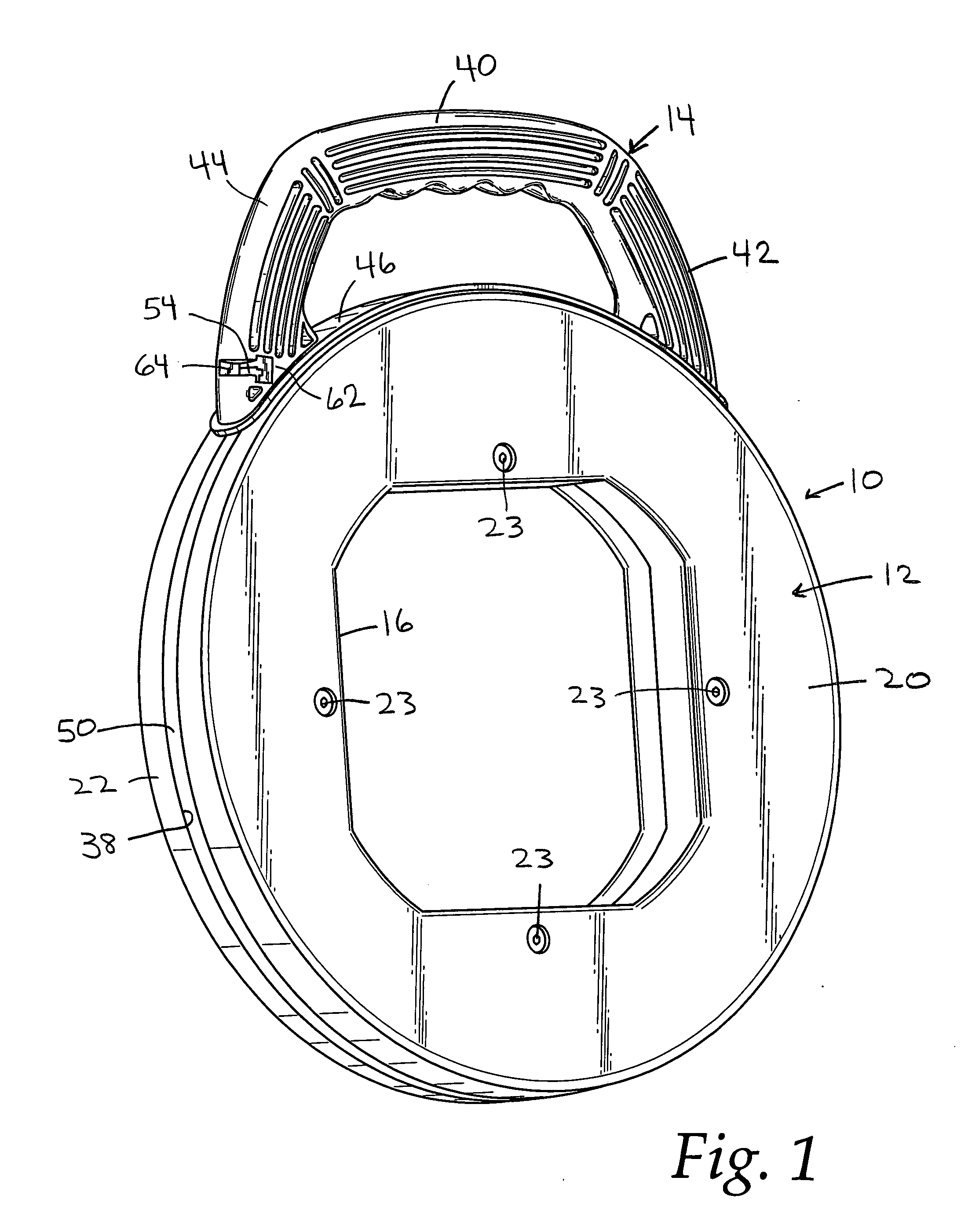
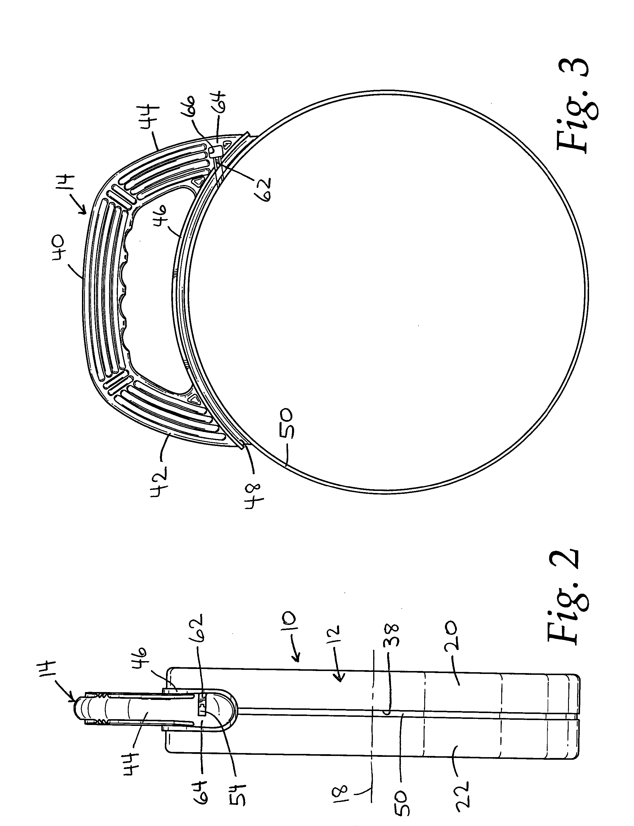
[0017] The fish tape assembly of the present invention is shown generally at 10 in FIGS. 1 and 2. The fish tape assembly 10 includes a generally circular case 12 and a handle 14. The case has a central opening 16 and defines an axis 18. The case 12 is made of first and second case halves 20 and 22. The case may be made of ABS, although other materials are possible. The halves are held together by four screws, shown schematically at 23, which extend through screw holes in one case half and into mounting posts in the other. For reference purposes the face of the fish tape assembly seen in FIG. 1 will be considered the front of the assembly.

[0018] Preferably the halves are identical so only half 20 will be described in connection with FIGS. 8 and 9. Like parts will be given like reference numerals in the two halves. The case half includes a radial wall 24 in the shape of a flat ring. An outer annular half wall 26 is attached to the outside edge of the radial wall 24. The annular half ...


PUM


Abstract

A fish tape assembly has a handle slidably mounted on a case formed by a pair of case halves. The periphery of the case has a gap formed therein. The handle has an exterior grip and shoe with a web extending from the shoe through the gap in the case to an interior belt. The belt is continuous around the full circumference of the case to provide increased strength and a shield that precludes a fish tape inside the case from inadvertently popping out through the gap. The handle has a passageway for the tape. The passageway includes a pair of laterally disposed posts that prevent the tape from popping out of the passageway.

Description

BACKGROUND OF THE INVENTION [0001] The present invention relates generally to an electrician's fish tape assembly. More specifically, the invention relates to a fish tape housing and an improved handle therefor. [0002] A fish tape is an electrician's tool which is used to install wires in a conduit. The fish tape itself is an elongated member made of tempered spring steel, stainless steel, nylon, fiberglass with a nylon jacket, or multi-stranded steel wire. The fish tape is rigid enough to be pushed through a conduit yet flexible enough to bend around corners or curves in the conduit. After the tape has been “fished” or threaded through a conduit, a wire or cable is attached to the end of the fish tape and the tape is pulled back through the conduit, drawing the wire with it to install the wire in the conduit. [0003] Fish tapes are supplied in lengths ranging from 25 to 240 feet. Due to the length of the fish tape, it is usually coiled for manageability. However, the natural resilie...

Claims


Application Information

Patent Timeline
Patent Type & Authority Applications(United States)
IPC IPC(8): B65H59/00B66F3/00H02G1/08H02G3/00H02G11/02
CPCB65H75/406B65H2402/412H02G11/02H02G1/083H02G1/085B65H2701/376
Inventor KONEN, BRUCE P.SWEDBERG, BENJAMIN D.
Owner IDEAL IND INC
Why Eureka
Try Eureka