Variable drive for printhead

a variable drive and printhead technology, applied in the field of variable drive for printhead, can solve the problems of increased interconnection complexity, increased complexity of driving firing resistors, and increased cost of interconnection complexity and performan

Inactive Publication Date: 2005-03-24
HEWLETT PACKARD DEV CO LP
View PDF9 Cites 50 Cited by
  • Summary
  • Abstract
  • Description
  • Claims
  • Application Information

AI Technical Summary

Problems solved by technology

There has been a trend toward increasing the number of firing chambers and associated resistors on the printhead, leading to increased complexity in driving the firing resistors.
Firing only one resistor at a time by a given driver reduces or prevents energy variation error terms that may occur due to parasitic effects, but at the expense of increased interconnection complexity and performance.

Method used


Image

  • Variable drive for printhead
  • Variable drive for printhead
  • Variable drive for printhead

Examples


Embodiment Construction

[0014] In the following detailed description and in the several figures of the drawing, like elements are identified with like reference numerals.

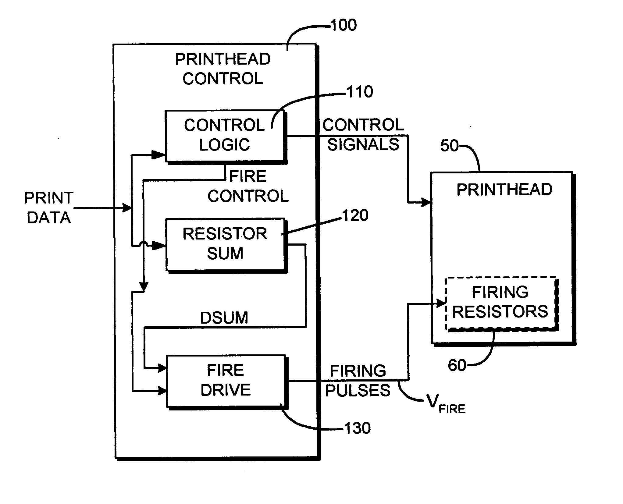
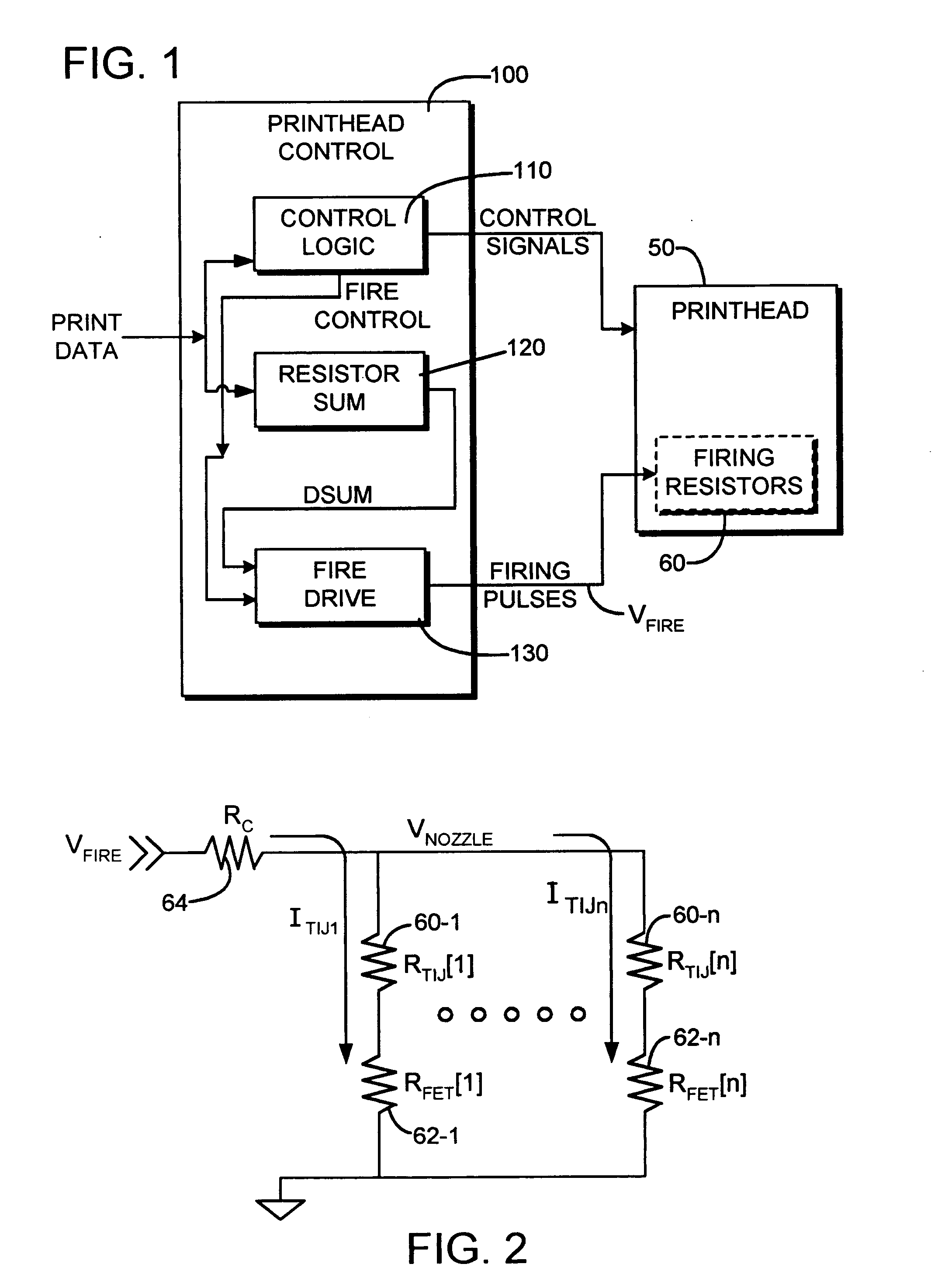
[0015] An embodiment of a printhead firing arrangement is illustrated in simplified form in FIG. 1. An inkjet printhead 50 has a set of firing resistors 60 which are energized to fire droplets of fluid, e.g. ink, from respective firing chambers through respective nozzles, as is known in the art. The printhead 50 in this exemplary embodiment receives a set of control signals and a set of firing pulses from a printhead control 100. The control signals select the particular resistors to be fired during a firing cycle, and the firing pulses are applied to the resistors selected to be fired.

[0016] In this exemplary embodiment, the control signals and the firing pulses are provided by a printhead control circuit 100. The circuit 100 receives the print data which identify the firing pattern for successive firing cycles. This data is converted b...


PUM


Abstract

A driver for driving simultaneously a variable number of firing resistors for a printhead includes a drive circuit for supplying a drive signal for firing the variable number of firing resistors, and a circuit for adjusting a voltage or current magnitude of the drive signal in dependence on the variable number of firing resistors to be fired simultaneously.

Description

BACKGROUND OF THE DISCLOSURE [0001] Thermal inkjet printheads employ drop ejectors which include firing resistors to vaporize fluid in firing chambers, resulting in droplet ejection through nozzles respectively associated with the firing chambers. There has been a trend toward increasing the number of firing chambers and associated resistors on the printhead, leading to increased complexity in driving the firing resistors. In the past, multiple drivers have typically been used to apply the firing signals to different groups of firing resistors. Firing only one resistor at a time by a given driver reduces or prevents energy variation error terms that may occur due to parasitic effects, but at the expense of increased interconnection complexity and performance. For these and other reasons, there is a need for the present invention. SUMMARY OF THE DISCLOSURE [0002] A driver for driving simultaneously a variable number of firing resistors for a printhead includes a drive circuit for sup...

Claims


Application Information

Patent Timeline
Patent Type & Authority Applications(United States)
IPC IPC(8): B41J2/05
CPCB41J2/04541B41J2/04545B41J2/04568B41J2/04591B41J2/04588B41J2/0459B41J2/0458
Inventor EATON, WILLIAM S.
Owner HEWLETT PACKARD DEV CO LP
Why Eureka
Try Eureka