Eureka AIR delivers breakthrough ideas for toughest innovation challenges, trusted by R&D personnel around the world.

Vent stay for a canopy or tent

Inactive Publication Date: 2005-03-31
THE COLEMAN CO INC
View PDF23 Cites 15 Cited by
  • Summary
  • Abstract
  • Description
  • Claims
  • Application Information

AI Technical Summary

Benefits of technology

[0012] The following presents a simplified summary of some embodiments of the invention in order to provide a basic understanding of the invention. This summary is not an extensive overview of the invention. It is not intended to identify

Problems solved by technology

Because a tent is often a closed structure, often the air within the tent becomes stale.
Although the mesh and rain fly construction of tents works well, the rain fly does not always provide optimal ventilation.
Often, the rain fly extends almost to the ground and if a breeze is not directed properly between the tent and the rain fly, the air and condensation may still accumulate underneath the rain fly and proper ventilation may not be supplied.
One problem with this particular vent structure was that the flexibility of the plastic strip often caused it to have a poor appearance or to collapse during wind or rain, preventing air from moving through the vent.
Although the vents for rain flies described above worked well for their intended purpose, in practice, users often forgot to connect the two fasteners to one another prior to assembling the tent.
Reaching the fasteners after the tent was assembled was difficult, if not impossible, and thus the user may have had to remove the fly to fasten the two strips.

Method used


Image

  • Vent stay for a canopy or tent
  • Vent stay for a canopy or tent
  • Vent stay for a canopy or tent

Examples


Embodiment Construction

[0023] In the following description, various embodiments of the present invention will be described. For purposes of explanation, specific configurations and details are set forth in order to provide a thorough understanding of the embodiments. However, it will also be apparent to one skilled in the art that the present invention may be practiced without the specific details. Furthermore, well-known features may be omitted or simplified in order not to obscure the embodiment being described.

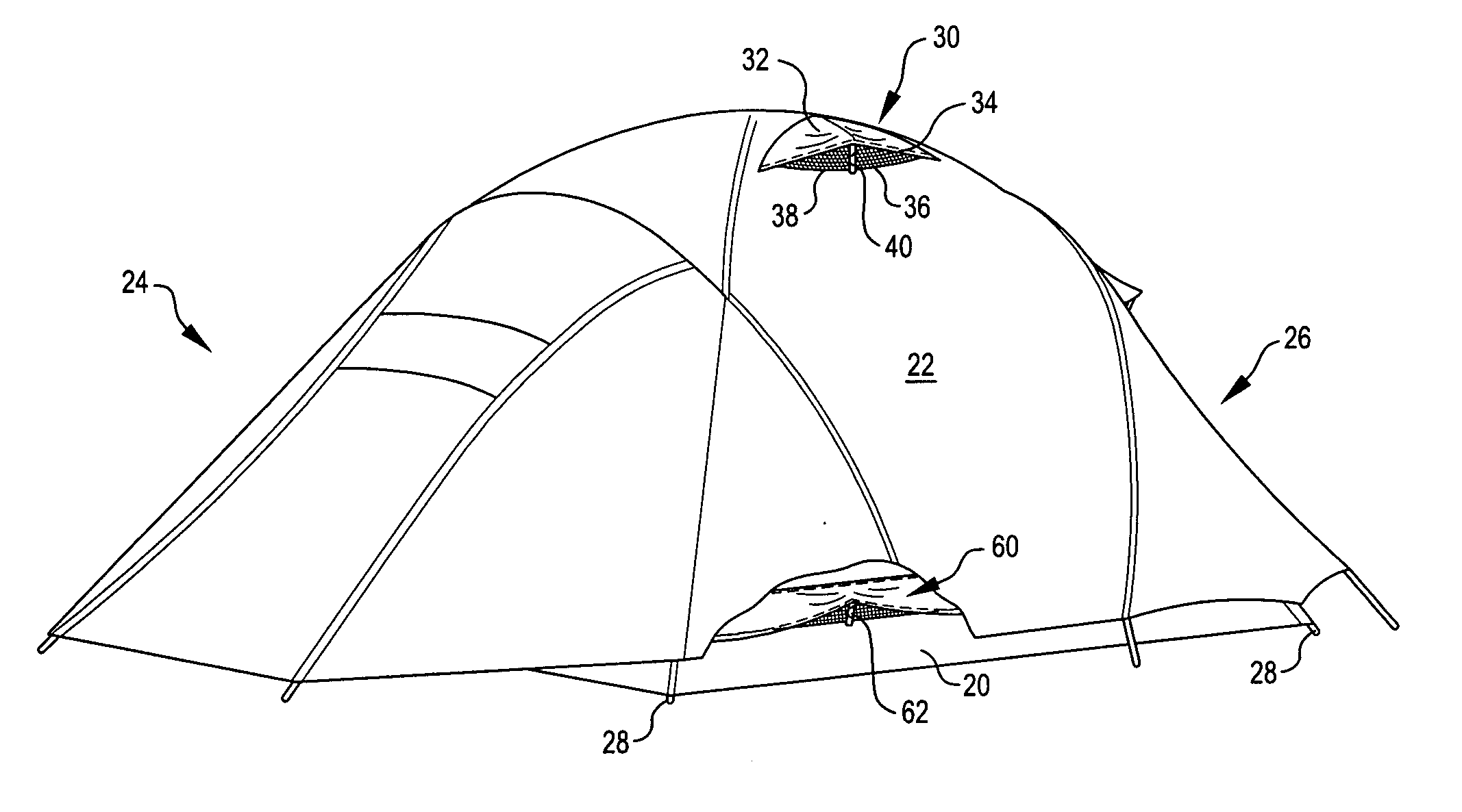
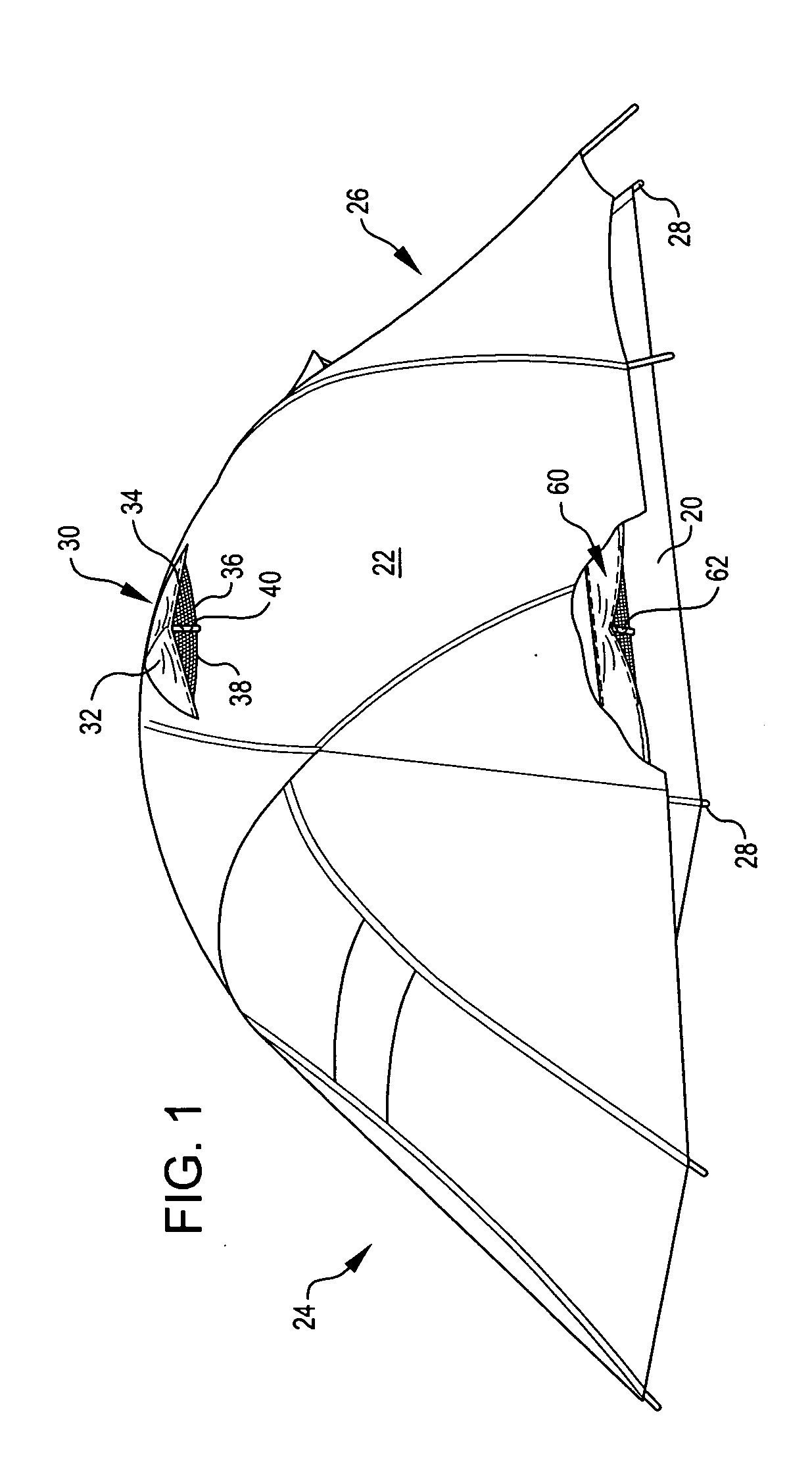
[0024] Referring now to the drawings, in which like reference numerals represent like parts throughout the several views, FIG. 1 shows a tent 20 having a rain fly 22, each of which incorporates a vent in accordance with an embodiment of the present invention. The rain fly 22 covers the tent 20 and forms a front vestibule 24 and a rear vestibule 26 for the tent 20.

[0025] As is known, modern tents (e.g., the tent 20) typically include a pole structure 28 (end of the poles for the structure are sh...


PUM


Abstract

A vent is provided on the lower portion of a tent. The lower portion is formed of a water-repellent material, and mesh material is provided at an upper portion of the tent. The vent may or may not use the stay described above. A flexible stay is also provided for a tent or canopy. The flexible stay is connected to upper and lower sections of a vent, and is formed of a construction that is resilient enough to support the vent during use, but is flexible enough so that the vent may be collapsed during storage.

Description

TECHNICAL FIELD OF THE INVENTION [0001] The present invention is directed to tents or canopies, and more specifically to a vent for use with a tent or canopy. BACKGROUND OF THE INVENTION [0002] Camping is a popular recreational activity enjoyed by many. Some people camp so that they may enjoy the outdoors, and others use camping as an inexpensive alternative to staying in a hotel. [0003] Often campers stay in a tent, either in a campsite, or in a suitable location somewhere outdoors. In general, a tent is a collapsible shelter, which typically is made of a tough fabric or plastic and is held up by poles or another suitable structure. [0004] Because a tent is often a closed structure, often the air within the tent becomes stale. Condensation, stale air, and aroma from a fetid tentmate is often expelled by providing tent ventilation. This ventilation can be provided, for example, by keeping the doors slightly open or by having windows in the tent. More recently, tents have been design...

Claims


Application Information

Patent Timeline
IPC IPC(8): E04H15/16E04H15/32
CPCE04H2015/326E04H15/16
Inventor WORLEY, LAUREN D.HOLUB, TIMOTHY M.
Owner THE COLEMAN CO INC
Why Eureka
Eureka Blog
Learn More