Fitting for fuel tanks

a technology for fuel tanks and fittings, applied in the direction of hose connections, couplings, machines/engines, etc., can solve the problems of fuel-tank fittings b>100/b> not achieving satisfactory fuel sealing ability for fuel tanks, and difficult molding

Inactive Publication Date: 2005-03-31
TOYODA GOSEI CO LTD
View PDF16 Cites 15 Cited by
  • Summary
  • Abstract
  • Description
  • Claims
  • Application Information

AI Technical Summary

Benefits of technology

[0008] The present invention has been developed and completed in view of such circumstances. It is therefore an object of the present invention to provide a fitting for fuel tanks which can secure a predetermined fuel-sealing ability for fuel tanks upon being subjected to shocks.

Problems solved by technology

Accordingly, there arises a fear that cracks “a” and “b” occur, for example.
Thus, it is feared that the fuel-tank fitting 100 might not secure a satisfactory fuel-sealing ability for the fuel tank 106 upon being subjected to shocks.
However, when the fuel-tank fitting 100 is thickened, it is difficult to carry out the molding.
Moreover, there is a fear that molding shrinkage might result in the occurrence of sink marks.

Method used


Image

  • Fitting for fuel tanks
  • Fitting for fuel tanks
  • Fitting for fuel tanks

Examples


example no.1

Example No. 1

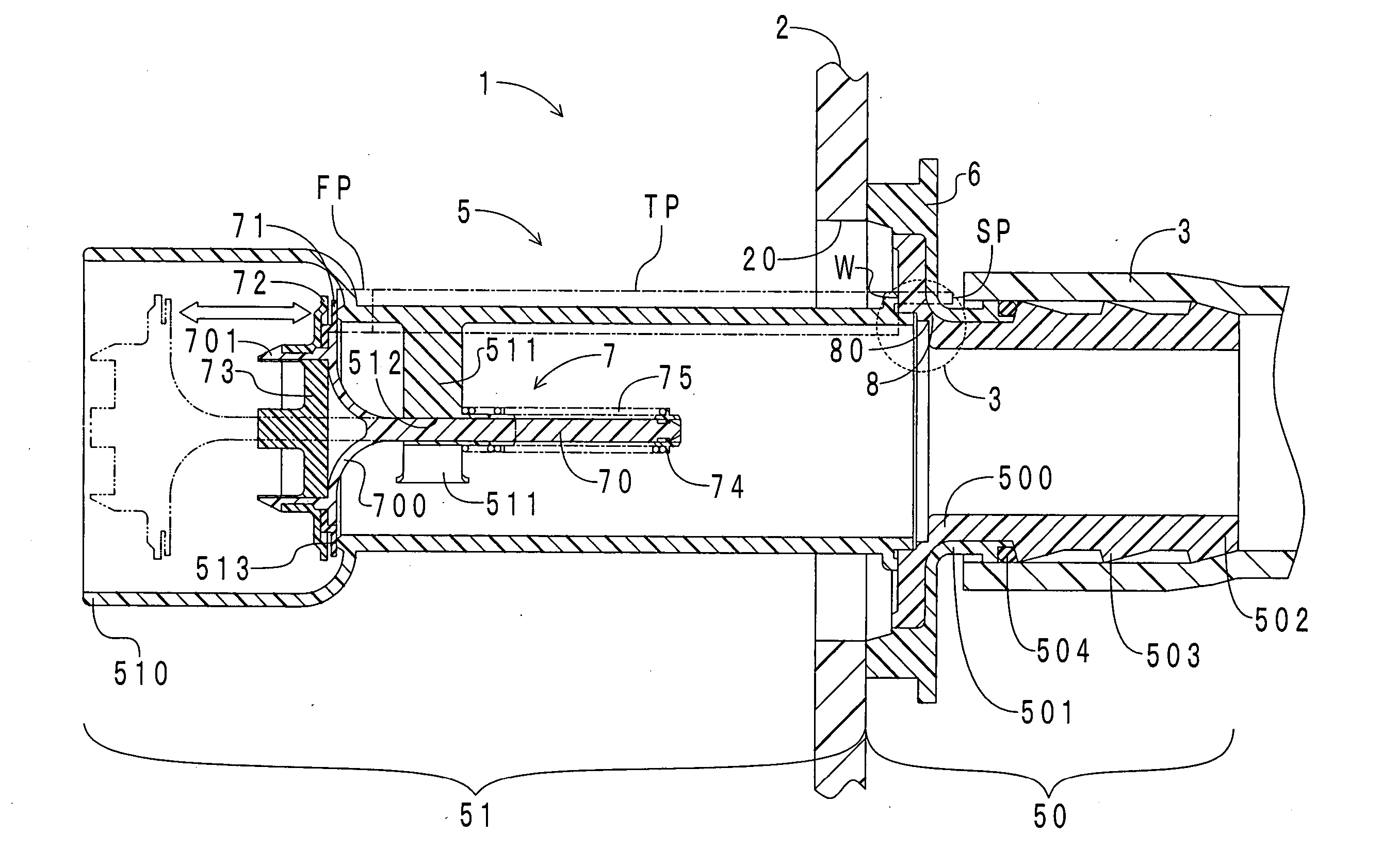
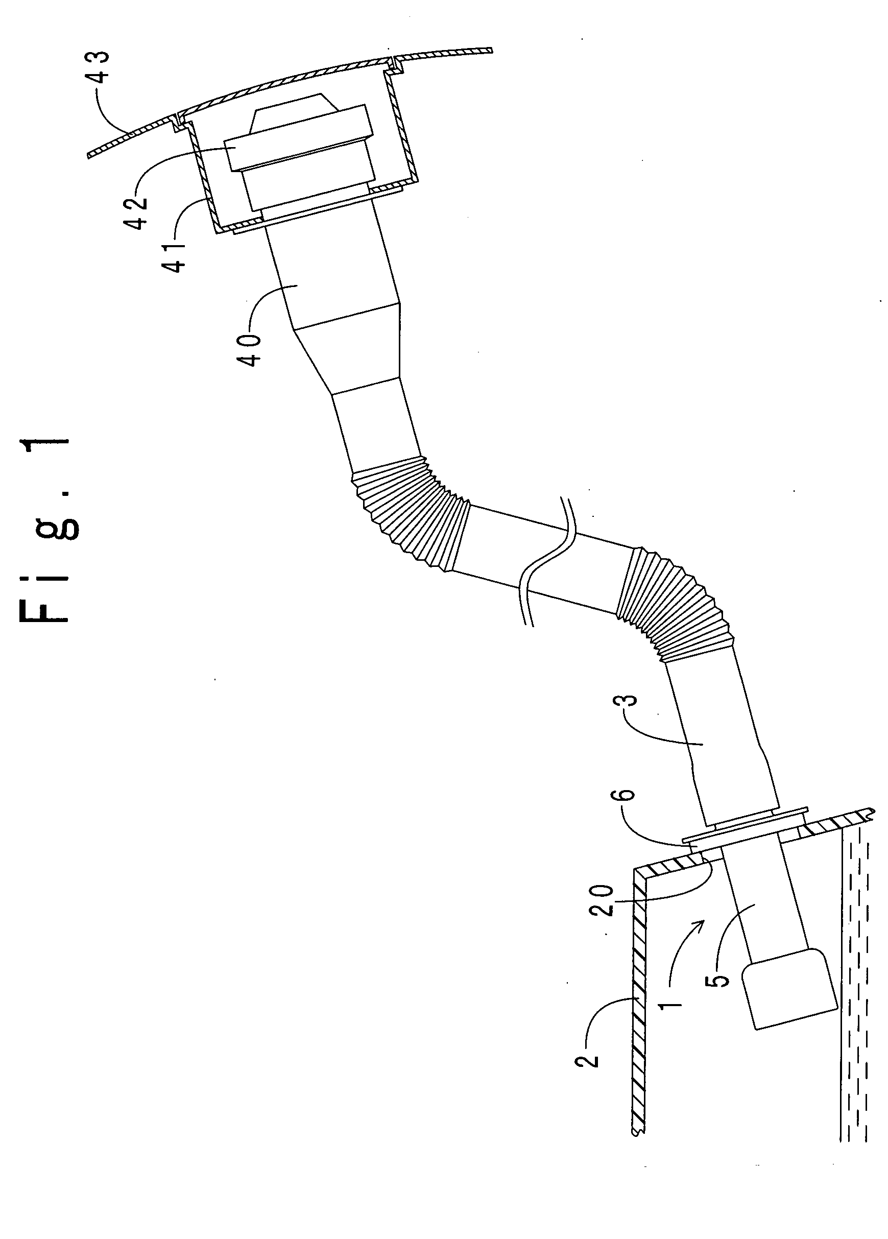
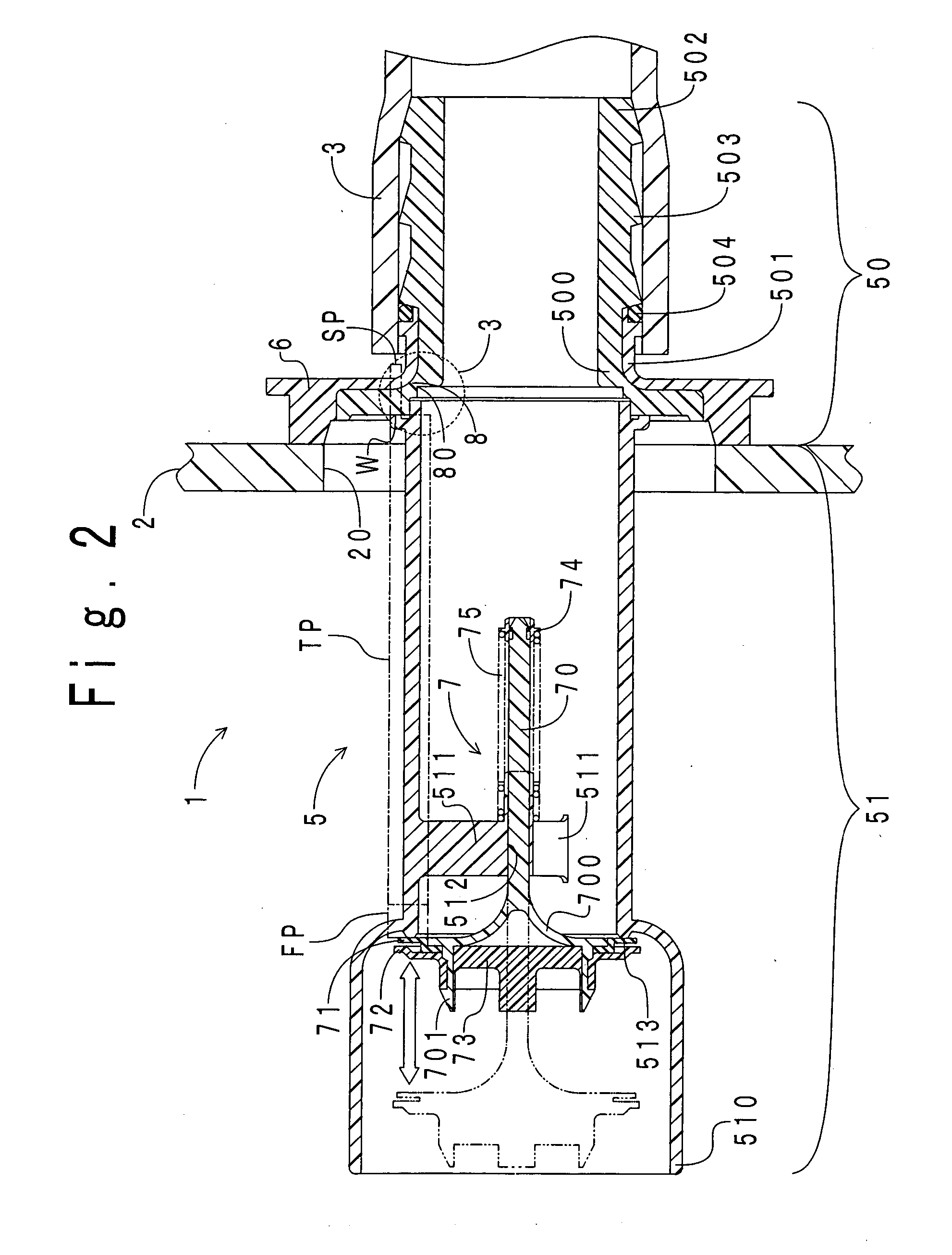
[0036] First, the arrangement of a fuel-tank fitting according to Example No. 1 of the present invention will be hereinafter described in detail. FIG. 1 illustrates an installation diagram for depicting how the fuel-tank fitting according to Example No. 1 is installed to a fuel tank. As shown in the drawing, a fuel-tank fitting 1 is disposed to cover an installation opening 20 opened through a fuel tank 2. A filler pipe 3 is connected with the upstream end of the fuel-tank fitting 1. Note that the present pipe includes the filler pipe 3. An inlet pipe 40 is connected with the upstream end of the filler pipe 3. The upstream-side portion of the inlet pipe 40 protrudes into an inlet box 41 recessed in a vehicle panel 43. A filler opening (not shown) is opened at the upstream end of the inlet pipe 40. A filler cap 42 is screwed into the filler opening. A fuel is supplied to the fuel tank 2 through the filler opening by way of the inlet pipe 40, the filler pipe 3 and the fue...

example no.2

Example No. 2

[0053] A fuel-tank fitting 1 according to Example No. 2 of the present invention differs from the fuel-tank fitting 1 according to Example No. 1 in that a groove formed in the outer periphery of the projection makes the fragile portion. Therefore, only the difference will be hereinafter described. FIG. 6 illustrates an axial cross-sectional view of the fuel-tank fitting 1 according to Example No. 2. FIG. 7 illustrates an enlarged diagram of a portion of the fuel-tank fitting 1 according to Example No. 2 within the circle “7” of FIG. 6 designated with a dotted line. In FIGS. 6 and 7, note that parts like those of FIGS. 2 and 3 are designated at the same reference numerals.

[0054] As can be appreciated from the drawings, the fragile portion 8 of the fuel-tank 1 according to Example No. 2 is disposed closer to the filler pipe 3 than that of the fuel-tank 1 according to Example No. 1 is (see FIG. 2). The fragile portion 8 is formed by radially carving a groove (i.e., the ha...

example no.3

Example No. 3

[0056] A fuel-tank fitting 1 according to Example No. 3 of the present invention differs from the fuel-tank fitting 1 according to Example No. 1 in that the projection 50 is fitted into a rubber hose, not into the resinous filler pipe 3. Therefore, only the difference will be hereinafter described. FIG. 8 illustrates an axial cross-sectional view of the fuel-tank fitting 1 according to Example No. 3. In FIG. 8, note that parts like those of FIG. 2 are designated at the same reference numerals. As shown in the drawing, a metallic collar 32 is fitted into and engaged with the inner periphery 500. Moreover, the projection 50 is fitted into a rubber hose 30 by press-in fitting. The rubber hose 30 is connected with a filler pipe (not shown), which communicates with a filler opening, at the upstream end. A metallic clamp 31 fastens the rubber hose 30 to the projection 50. The fastening secures a fuel-sealing ability between the projection 50 and the rubber hose 30.

[0057] The...


PUM


Abstract

A fuel-tank fitting includes a cylinder-shaped fitting body including a connecting end to be connected with a pipe and a free end to be disposed freely inside a fuel tank, a flange disposed on an outer peripheral surface of the fitting body, and fastened to an opening periphery of an installation opening opened through the fuel tank, and a check valve disposed in the fitting body, openable only in a direction heading from the connecting end of the fitting body to the free end thereof, and closable for sealing a fuel. The fitting body further includes a first portion sealing the check valve, a second portion fastened to a portion of the flange, a third portion connecting the first and second portions, and a fragile portion fracturing more preferentially than the first and second portions and the flange fracture while securing a fuel-sealing ability inside the fuel tank.

Description

BACKGROUND OF THE INVENTION [0001] 1. Field of the Invention [0002] The present invention relates to a fitting for fuel tanks which is intervened between a fuel tank and a pipe. [0003] 2. Description of the Related Art [0004] Conventionally, rubber hoses have been intervened between a resinous filler pipe, which is communicated with a filler opening, and a fuel-tank fitting, which is installed to a fuel tank. Recently, a fuel-tank fitting has been developed which is connected directly with a filler pipe, for example, one which is disclosed in Japanese Unexamined Patent Publication (KOKAI) NO. 2002-54,519. FIG. 13 illustrates an axial cross-sectional view of the fuel-tank fitting set forth in the publication. As shown in the drawing, a fuel-tank fitting 100 comprises a fitting body 101, a flange 102, and a check valve 103. The fitting body 101 comprises a projection 107, and an accommodation 108. The projection 107 protrudes to the outside of a fuel tank 106. A connecting end 104 is ...

Claims


Application Information

Patent Timeline
Patent Type & Authority Applications(United States)
IPC IPC(8): B60K15/04F02M37/00F16K15/06
CPCB60K2015/03447B60K15/04Y10T137/8811Y10T137/86372
Inventor KANEKO, KENICHIRO
Owner TOYODA GOSEI CO LTD
Why Eureka
Try Eureka