Fitting for fuel tanks
a technology for fuel tanks and fittings, applied in the direction of hose connections, couplings, machines/engines, etc., can solve the problems of fuel-tank fittings b>100/b> not achieving satisfactory fuel sealing ability for fuel tanks, and difficult molding
- Summary
- Abstract
- Description
- Claims
- Application Information
AI Technical Summary
Benefits of technology
Problems solved by technology
Method used
Image
Examples
example no.1
Example No. 1
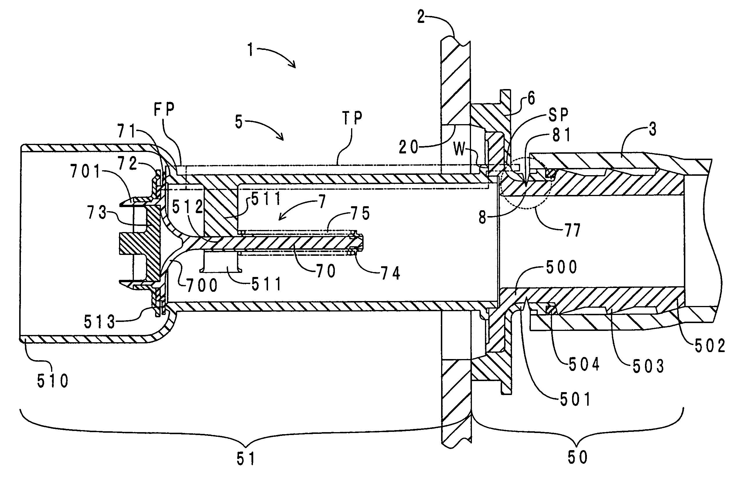
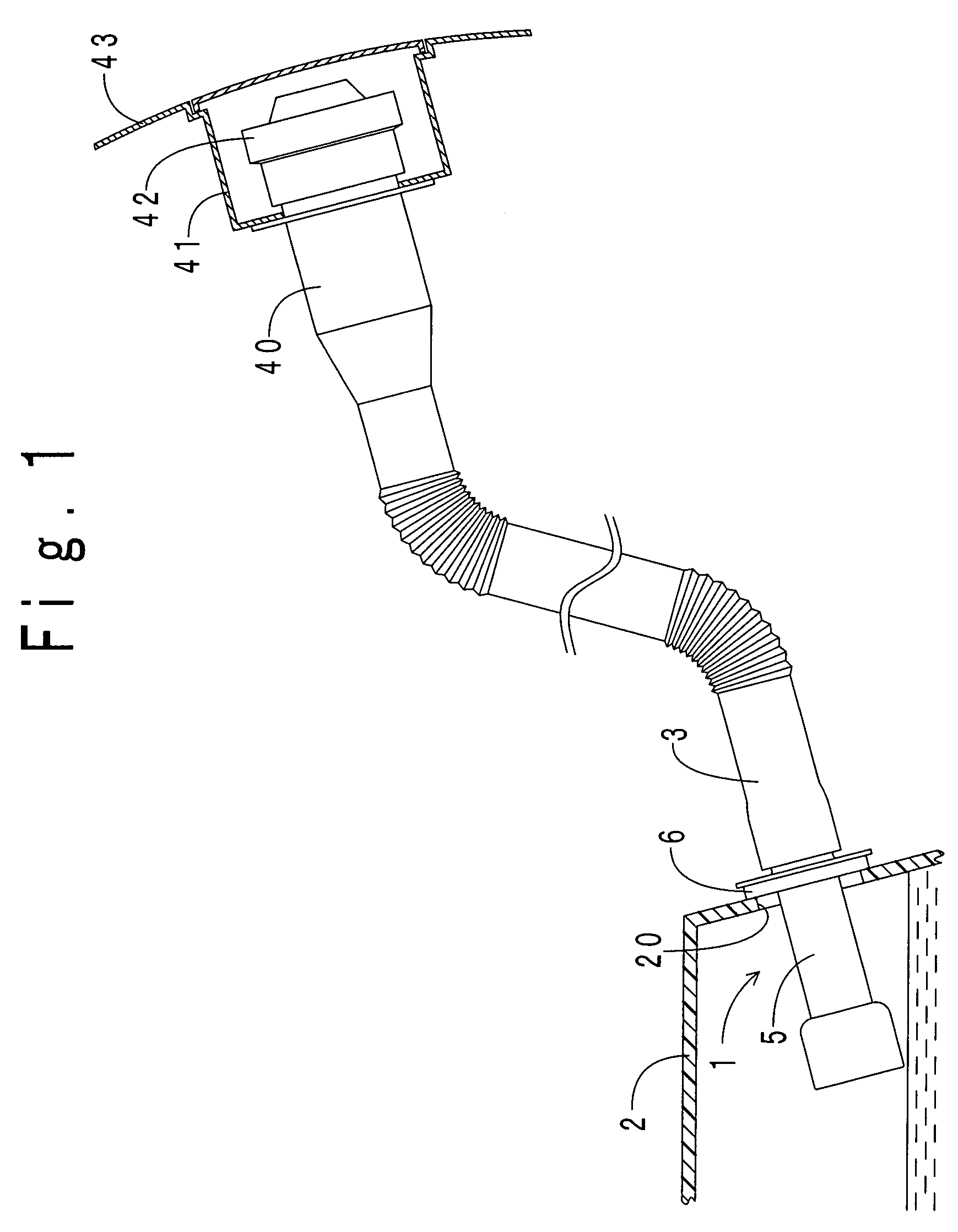
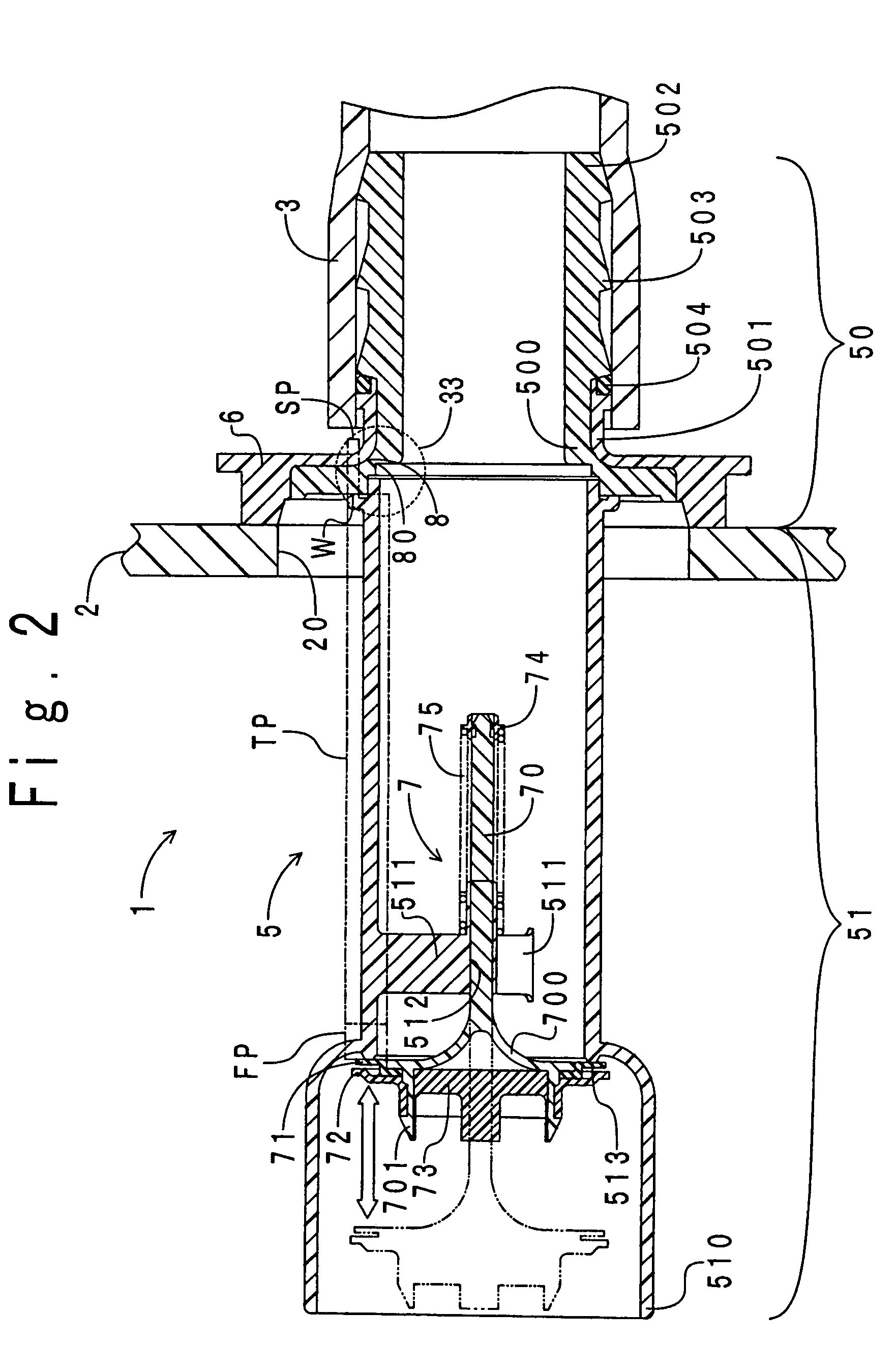
[0036]First, the arrangement of a fuel-tank fitting according to Example No. 1 of the present invention will be hereinafter described in detail. FIG. 1 illustrates an installation diagram for depicting how the fuel-tank fitting according to Example No. 1 is installed to a fuel tank. As shown in the drawing, a fuel-tank fitting 1 is disposed to cover an installation opening 20 opened through a fuel tank 2. A filler pipe 3 is connected with the upstream end of the fuel-tank fitting 1. Note that the present pipe includes the filler pipe 3. An inlet pipe 40 is connected with the upstream end of the filler pipe 3. The upstream-side portion of the inlet pipe 40 protrudes into an inlet box 41 recessed in a vehicle panel 43. A filler opening (not shown) is opened at the upstream end of the inlet pipe 40. A filler cap 42 is screwed into the filler opening. A fuel is supplied to the fuel tank 2 through the filler opening by way of the inlet pipe 40, the filler pipe 3 and the fuel...
example no.2
Example No. 2
[0053]A fuel-tank fitting 1 according to Example No. 2 of the present invention differs from the fuel-tank fitting 1 according to Example No. 1 in that a groove formed in the outer periphery of the projection makes the fragile portion. Therefore, only the difference will be hereinafter described. FIG. 6 illustrates an axial cross-sectional view of the fuel-tank fitting 1 according to Example No. 2. FIG. 7 illustrates an enlarged diagram of a portion of the fuel-tank fitting 1 according to Example No. 2 within the window 77 of FIG. 6, which is designated with a dotted line. In FIGS. 6 and 7, note that parts like those of FIGS. 2 and 3 are designated at the same reference numerals.
[0054]As can be appreciated from the drawings, the fragile portion 8 of the fuel-tank 1 according to Example No. 2 is disposed closer to the filler pipe 3 than that of the fuel-tank 1 according to Example No. 1 is (see FIG. 2). The fragile portion 8 is formed by radially carving a groove (i.e., ...
example no.3
Example No. 3
[0056]A fuel-tank fitting 1 according to Example No. 3 of the present invention differs from the fuel-tank fitting 1 according to Example No. 1 in that the projection 50 is fitted into a rubber hose, not into the resinous filler pipe 3. Therefore, only the difference will be hereinafter described. FIG. 8 illustrates an axial cross-sectional view of the fuel-tank fitting 1 according to Example No. 3. In FIG. 8, note that parts like those of FIG. 2 are designated at the same reference numerals. As shown in the drawing, a metallic collar 32 is fitted into and engaged with the inner periphery 500. Moreover, the projection 50 is fitted into a rubber hose 30 by press-in fitting. The rubber hose 30 is connected with a filler pipe (not shown), which communicates with a filler opening, at the upstream end. A metallic clamp 31 fastens the rubber hose 30 to the projection 50. The fastening secures a fuel-sealing ability between the projection 50 and the rubber hose 30.
[0057]The fu...
PUM
 Abstract
Description
Claims
Application Information
 - R&D
- Intellectual Property
- Life Sciences
- Materials
- Tech Scout
- Unparalleled Data Quality
- Higher Quality Content
- 60% Fewer Hallucinations
Browse by: Latest US Patents, China's latest patents, Technical Efficacy Thesaurus, Application Domain, Technology Topic, Popular Technical Reports.
© 2025 PatSnap. All rights reserved.Legal|Privacy policy|Modern Slavery Act Transparency Statement|Sitemap|About US| Contact US: help@patsnap.com


