Opener for producing hole in side of pressurized beverage can

a technology for opening and forming holes, which is applied in the field of can openers, can solve the problems of uneven hole formation, very high risk of bodily injury,

Inactive Publication Date: 2005-04-14
YUREK JOHN TERRY JR +1
View PDF14 Cites 29 Cited by
  • Summary
  • Abstract
  • Description
  • Claims
  • Application Information

AI Technical Summary

Problems solved by technology

Needless to say, such a technique creates a very great risk of bodily injury during the formation of the opening.
Moreover, holes formed in such a manner tended to be uneven with sharp edges jutting outward from the can.

Method used


Image

  • Opener for producing hole in side of pressurized beverage can
  • Opener for producing hole in side of pressurized beverage can
  • Opener for producing hole in side of pressurized beverage can

Examples


Embodiment Construction

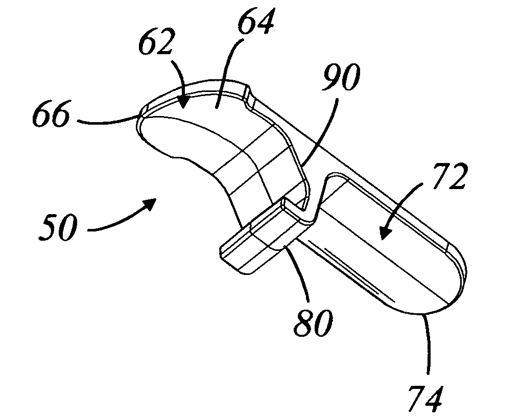
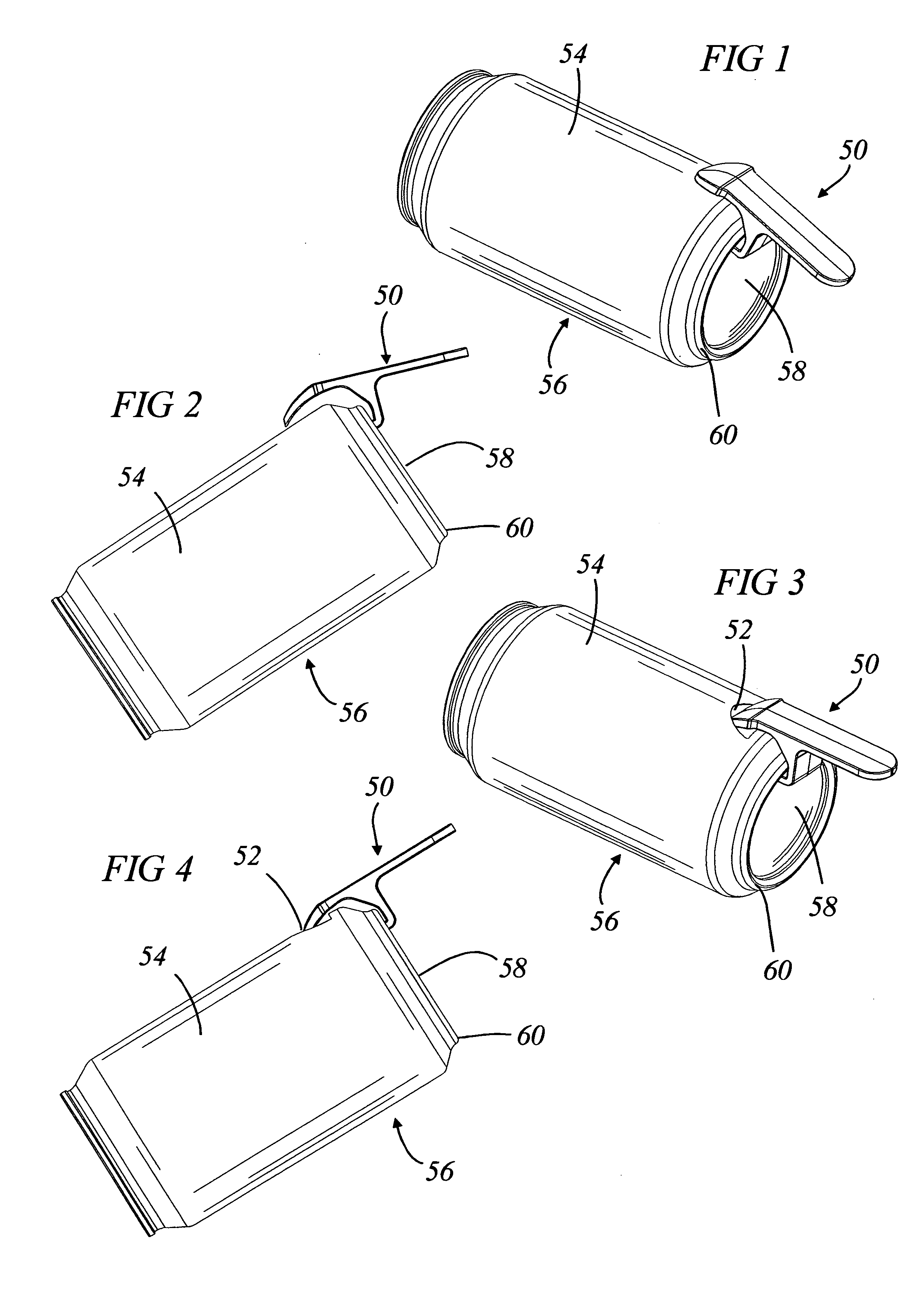
[0020] With reference now to FIGS. 1-9, an opener 50 is illustrated. The illustrated opener 50 is specifically adapted for use in forming an opening 52 in a side wall 54 of a beverage container 56. The bottom of the container 56 generally comprises a recess 58 defined in part by a rim 60. The opener 50 preferably is designed and configured to be oriented relative to the rim 60. The opener 50 can be formed of any material but preferably is formed of injection molded plastic. In some configurations, the opener 50 can be formed of metal or other materials in any suitable manner.

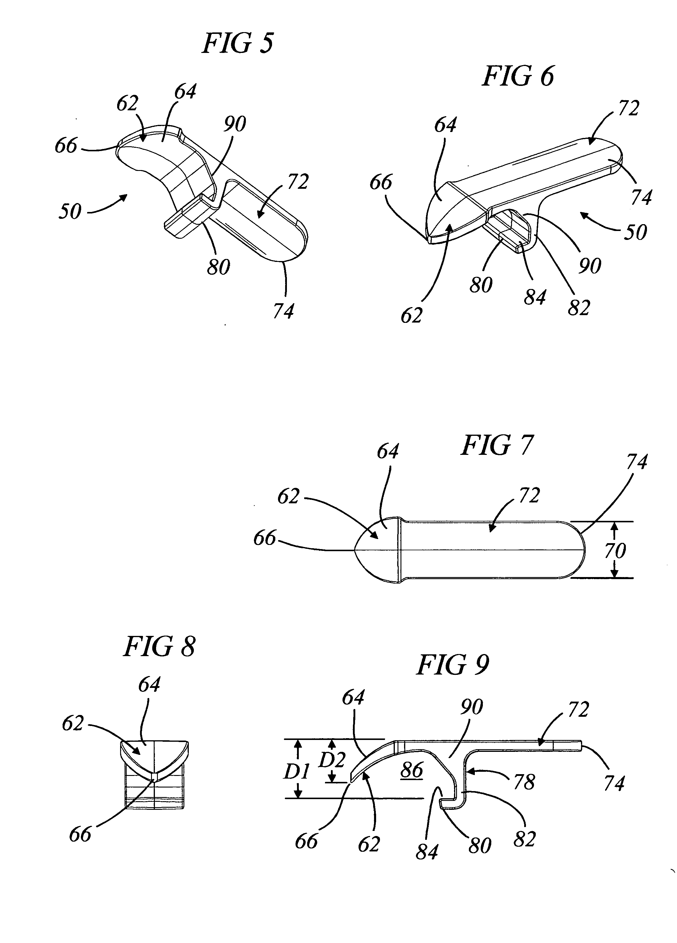
[0021] With reference to FIG. 1, the opener 50 generally comprises a piercing tip 62. The piercing tip 62 advantageously is designed to form the opening 52 in the side wall 54 of the beverage container. In the illustrated arrangement, the tip 62 comprises a generally triangular body 64. The body 64, in turn, comprises an apex 66 and a base 68 that is generally diametrically opposed to the apex 66. The body 64 p...


PUM


Abstract

An opener has a slightly rounded tip that is used to pierce a sidewall of a cylindrical container. The opener also has a hook that extends into a recess formed in a bottom surface of the container. The hook has a surface serves as a fulcrum for the opener to assist in formation of the opening in the sidewall of the container.

Description

RELATED APPLICATIONS [0001] This application hereby claims the priority benefit under 35 U.S.C. § 119(e) of U.S. Provisional Patent Application No. 60 / 509,547, filed on Oct. 9, 2003, which is hereby incorporated by reference in its entirety.BACKGROUND OF THE INVENTION [0002] 1. Field of the Invention [0003] The present invention generally relates to can openers. More particularly, the present invention relates to can openers that are configured to pierce a side wall of a pressurized beverage can. [0004] 2. Description of the Related Art [0005] Beer is often consumed at parties. One manner in which the beer is consumed has been commonly called “shot gunning” the beer. To “shot gun” beer, an opening is formed in the lower sidewall of the can while the can is generally inverted. Once the opening is formed in the lower sidewall of the can, the can is raised with the hole placed to the mouth of the consumer and with the top of the can positioned higher than the hole. The pull tab on the ...

Claims


Application Information

Patent Timeline
Patent Type & Authority Applications(United States)
IPC IPC(8): B67B7/16B67B7/48
CPCB67B7/24
Inventor YUREK, JOHN TERRY JR.MILLAR, DAVID ROBERT
Owner YUREK JOHN TERRY JR
Why Eureka
Try Eureka