U-turn and slowing to stop signals

Inactive Publication Date: 2005-04-21
LEVIN LENORA K
View PDF6 Cites 11 Cited by
  • Summary
  • Abstract
  • Description
  • Claims
  • Application Information

AI Technical Summary

Benefits of technology

[0007] In more generalized terms, a turn signal device, according to the present invention, for use on a vehicle having a turn signal, includes a human operated signal initiation device, at least one flasher device responsive to the human operated signal initiation device. The vehicle turn signal is responsive to the at least one flasher device, operating in a manner easily distinguishable from a conventional turn signal. The at least one flasher device causes the vehicle turn signal to operate in a combination of long and short light signals. In one arrangement, the at least one

Problems solved by technology

In a similar arrangement, the circuit causes the vehicle turn signal to operate in a combination of long and short light signals and a combination of long and short delays between the light signals.
In general, the circuit causes the vehicle turn signal to operate in a series of light signals and delays.
In one arrangement,

Method used


Image

  • U-turn and slowing to stop signals
  • U-turn and slowing to stop signals
  • U-turn and slowing to stop signals

Examples


Embodiment Construction

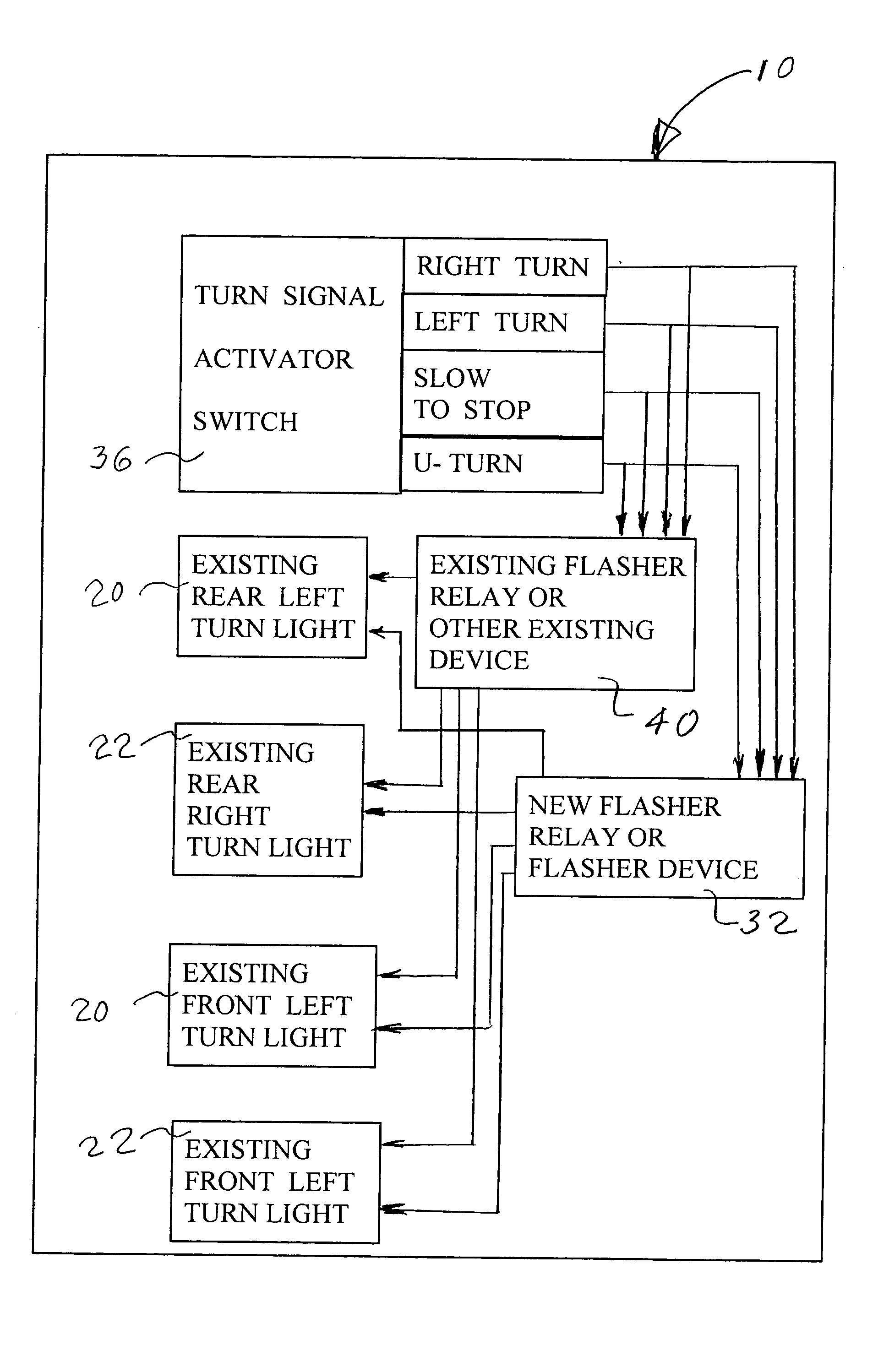
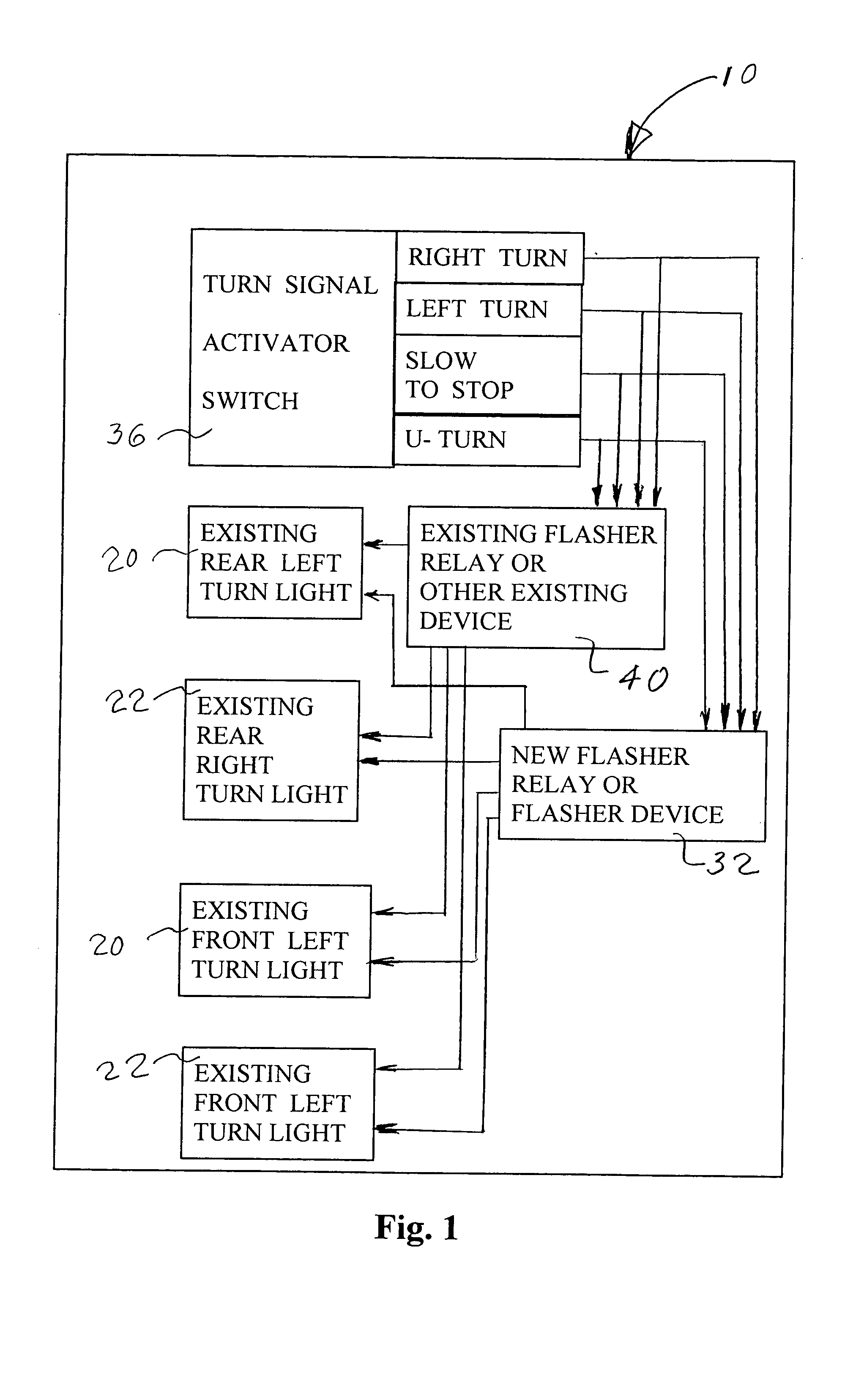
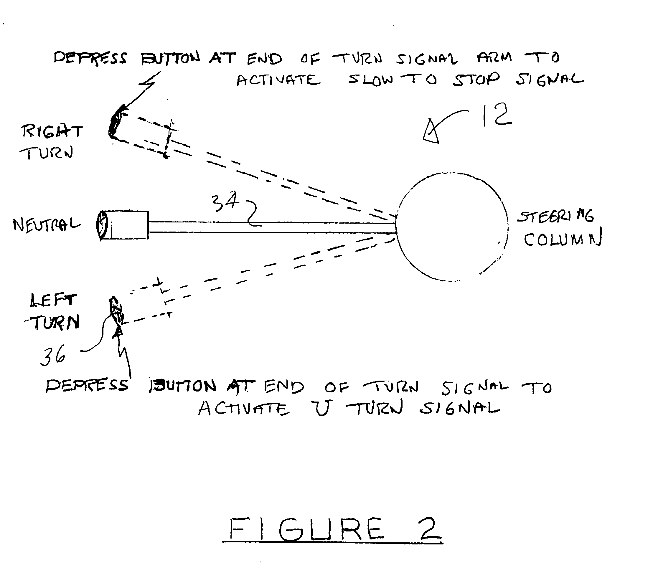
[0013] Referring now to the drawing, and in particular to FIG. 1, a turn signal circuit according to the present invention is referred to generally by reference numeral 10. Circuit 10. Referring also to FIG. 2 and FIG. 3, a turn signal device, according to the present invention, for use on a vehicle having a turn signal, includes a human operated signal initiation device 12, at least one flasher 14; and at least one delay device 16. The at least one flasher and the at least one delay device are connected in a circuit 18 which is responsive to the human operated signal initiation device. The vehicle turn signal 20 or 22 is responsive to the circuit, and the circuit causes the vehicle turn signal to operate in a manner easily distinguishable from a conventional turn signal. In one arrangement, the circuit causes the vehicle turn signal to operate in a combination of long and short light signals. In a similar arrangement, the circuit causes the vehicle turn signal to operate in a combi...


PUM


Abstract

A turn signal device, according to the present invention, for use on a vehicle having a turn signal, includes a human operated signal initiation device, at least one flasher; and at least one delay device. The at least one flasher and the at least one delay device are connected in a circuit which is responsive to the human operated signal initiation device. The vehicle turn signal is responsive to the circuit, and the circuit causes the vehicle turn signal to operate in a manner easily distinguishable from a conventional turn signal. In one arrangement, the circuit causes the vehicle turn signal to operate in a combination of long and short light signals. In a similar arrangement, the circuit causes the vehicle turn signal to operate in a combination of long and short light signals and a combination of long and short delays between the light signals. In general, the circuit causes the vehicle turn signal to operate in a series of light signals and delays. In a preferred form, wherein the circuit causes the vehicle turn signal to operate in a repeated series of two short light signals followed by one long light signal, with short delays after the short light signals and a long delay after the long light signal. Such a signal represents the letter “U” in Morse Code. A similar code could be used for a slow-to-stop signal. In general, the U-turn signal would be on the front and rear driver side turn signal and the slow-to-stop or pull-over-to-stop signal would be on the front and rear passenger side. In one particular embodiment, the at least one flasher comprises two short flashers and one long flasher in series. In one such embodiment, the at least one delay device comprises a short delay device in series with and after each of the two short flashers and a long delay device after the one long flasher. Normally, the long flasher is at least twice as long as a short flasher and the long delay device delays at least twice as long as a short delay device.

Description

BACKGROUND OF THE INVENTION [0001] 1. Field of the Invention [0002] The present invention relates generally to vehicle turn signals, and in particular, to signals for U-turns and slowing to stop. [0003] 2. Description of Related Art [0004] Most prior U-turn devices were mainly additional lights, either added as aftermarket devices or included in the original vehicle. Some, like U.S. Pat. Nos. 4,387,361; 5,003,289 and 6,195,001 show a signal mounted inside a car to be visible through a window. U.S. Pat. No. 5,680,100 includes a separate U-shaped lens over a separate signal light. U.S. Pat. Nos. 5,731,755 and 6,043,740 show the use of a series of lights that flash in a sequence to make a U-shape. [0005] U.S. Pat. No. 5,663,708 adds additional colored lights to existing left turn signals. SUMMARY OF THE INVENTION [0006] A turn signal device, according to the present invention, for use on a vehicle having a turn signal, includes a human operated signal initiation device, at least one fl...

Claims


Application Information

Patent Timeline
IPC IPC(8): B60Q1/34B60Q1/50
CPCB60Q1/50B60Q1/34
Inventor LEVIN, LENORA K.
Owner LEVIN LENORA K
Why Eureka
Try Eureka