Heating-type vacuum press device

a vacuum press and heating-type technology, applied in the field of vacuum press apparatus, can solve the problem that the apparatus is not suitable for a case, and achieve the effect of miniaturizing the vacuum pump

Active Publication Date: 2005-04-28
MIKADO TECHNOS
View PDF6 Cites 45 Cited by
  • Summary
  • Abstract
  • Description
  • Claims
  • Application Information

AI Technical Summary

Benefits of technology

[0027] The vacuum isolation chamber is formed by the base, the fitting plate, the lower fixed plate and the upper movement frame through descending the fitting plate toward the base. The very narrow vacuum isolation chamber can be formed by minimizing the vertical

Problems solved by technology

Thus, this apparatus is not suitable for a case where subtle adjustment and contro

Method used


Image

  • Heating-type vacuum press device
  • Heating-type vacuum press device
  • Heating-type vacuum press device

Examples


second embodiment

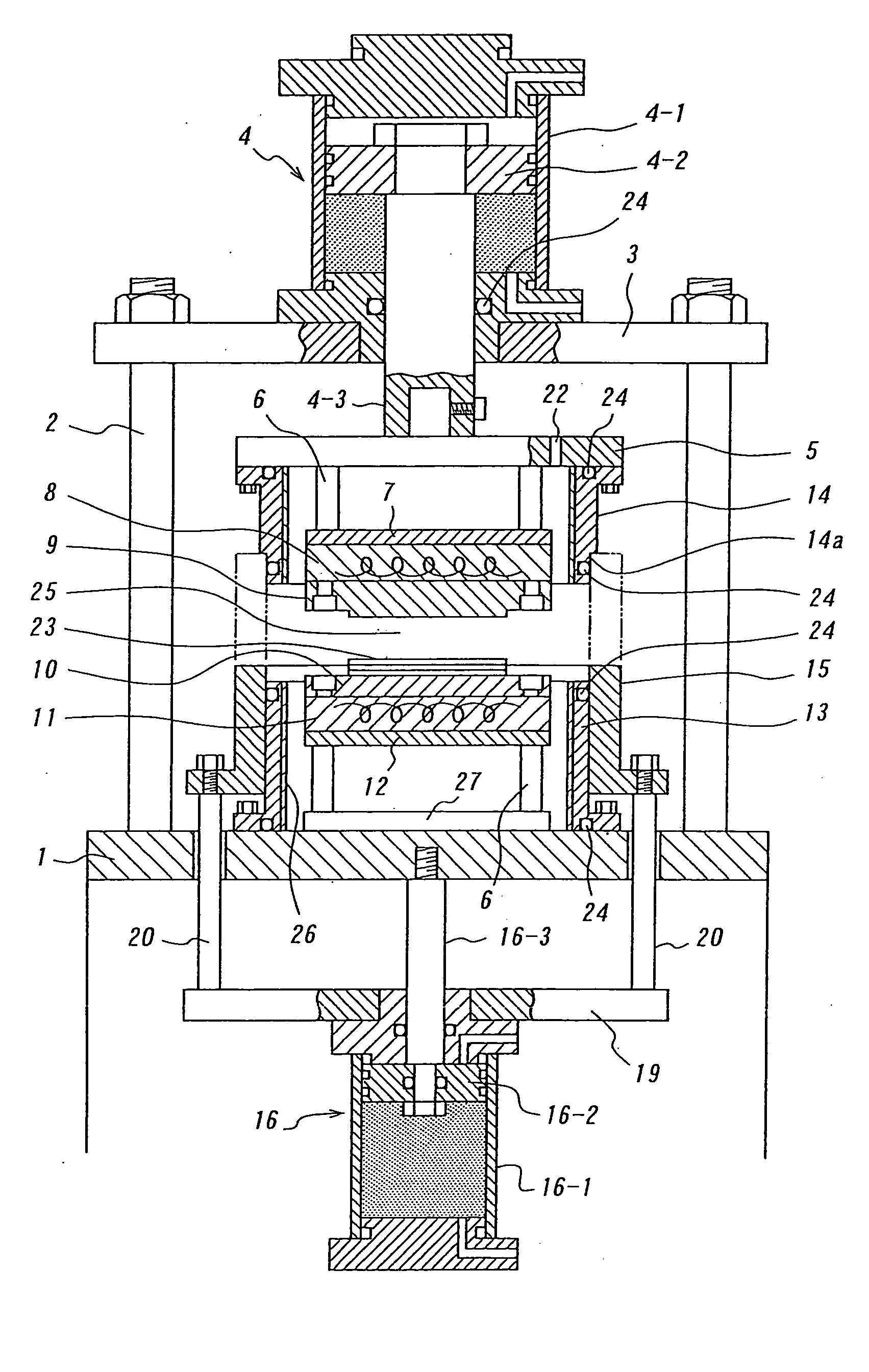
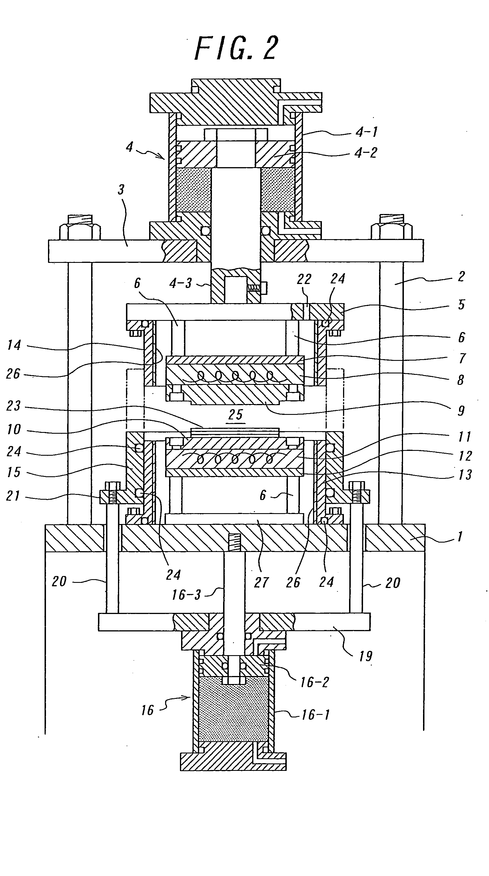
[0090]FIG. 2 is a partially sectional front elevation view schematically and entirely illustrating the heating-type vacuum press apparatus according to the present invention, and FIGS. 3 and 4 are functionally illustrating views thereof. The same reference numerals are given to the same or similar parts as in FIG. 1, and explanation thereof will be omitted.

[0091] In the present embodiment, a gas-tight sliding mechanism is a sliding frame 15 vertically slidably fitted around the outer peripheral face of a lower fixed frame 13, and a sliding mechanism is a sliding mechanism 16 for vertically sliding the sliding frame. Gas tightness among the lower fixed frame 13, the sliding frame 15 and the upper movement frame 14 is ensured by sliding the sliding frame 15 with the sliding mechanism 16. An isolation chamber 25 is formed in a space defined by the lower fixed frame 13, the sliding frame 15, the upper movement frame 14, a base 1 and a fitting plate 5. In this embodiment, a gas-tight sli...

third embodiment

[0097]FIG. 5 shows the heating-type vacuum press apparatus according to the present invention. As the sliding frame body is raised by driving the pushup cylinder 16, an upper end of the sliding frame body 15 closely slidably contacts a stepped portion 14a formed at an outer peripheral portion of the lower end of the upper movement frame 14, not the outer peripheral face of the upper movement frame 14. Thereby, an isolation chamber 25 is formed.

[0098] When the isolation chamber 25 is formed in this way, vacuum sucking is immediately effected through the suction hole 22 of the fitting plate 5 and simultaneously the pressing plate 9 is descended by driving the cylinder mechanism 4. At that time, the cylinder mechanism 4 may be turned to an open state (off). Since the interior of the isolation chamber 25 is in high vacuum, there is little possibility that the sliding frame body descends due to its self weight. The pushup cylinder mechanism 16 has only to be continuously driven in a dire...

fifth embodiment

[0109]FIG. 7 is a partially broken front elevation view of the heating-type vacuum press apparatus according to the present invention, and FIGS. 8a and 8b and FIGS. 9a and 9b are functionally illustrating views thereof. In this embodiment, a pressing plate is upwardly urged by a balancing cylinder mechanism for exclusive use thereof, and the weight of the pressing plate and a heater is prevented from being applied to a workpiece by the balancing cylinder mechanism when the pressing plate contacts the workpiece. In the following, featuring portions of this embodiment will be explained, while explanation of overlapping portions is omitted.

[0110] In the present embodiment, a driving unit 104, which is arranged on a supporting frame 3, comprises a high-pressure, large-diameter pull-up cylinder mechanism 104-1, a medium-pressure, medium-diameter balancing cylinder mechanism 104-2 and a low-pressure, small-diameter pressurizing cylinder mechanism 104-3, which are placed one upon another s...


PUM

PropertyMeasurementUnit
Weightaaaaaaaaaa

Abstract

A heating-type vacuum press device which has a small vacuum isolation chamber in which pressing is performed under vacuum without damage to seal packing, while heating. A lower fixed frame and an upper movement frame constitute a wall portion of the isolation chamber. A gas-tight sliding mechanism ensures gas-tightness between the lower fixed frame and the upper movement frame. Thereby, the isolation chamber is formed in a space defined by the lower fixed frame, the upper movement frame, a base and a fitting plate. The lower fixed frame surrounds a receiving table equipped with a heater for a workpiece, and is arranged on the base such that the lower fixed frame is spaced from the receiving table. The upper movement frame is hanged from the fitting plate such that the upper movement frame is spaced from a pressing plate equipped with a heater, and surrounds the pressing plate. The isolation chamber is sucked to vacuum, and a workpiece on the receiving plate is pressed under heating and vacuum at a high temperature with a low thrusting force by descending the pressing plate. The present apparatus is suitable for bonding multi-functional laminated films having high heat-resistant temperature.

Description

TECHNICAL FIELD [0001] The present invention relates to an apparatus for pressing under vacuum, while heating, in the state that an isolation chamber is formed by operating a press unit and high vacuum is realized in the isolation chamber. Particularly, the invention relates to the vacuum press apparatus suitable for pressing under high temperature and extremely low press pressure. BACKGROUND ART [0002] The present applicant formerly proposed a vacuum press apparatus for effecting press adhesion under heating at high vacuum while evacuation is performed, in bonding IC cards, print circuit boards, polarization lenses. See JP-A-2002-96199. In this apparatus, however, a sliding frame to form the isolation chamber is directly contacted with a jig containing a heater. Since the heat-withstanding temperature of seal packings (O-rings or the like) provided in the sliding frame is in a low temperature range of around 200° C. Therefore, such an apparatus cannot be used in case that pressing ...

Claims


Application Information

Patent Timeline
IPC IPC(8): B30B12/00B29C43/36B29C43/52B29C43/56B30B1/32B30B15/34B32B38/00
CPCB29C33/08B29C33/20B29C43/32B29C43/36B29C43/52Y10S425/127B29C2043/561B29K2105/256B32B37/10B32B38/0036B32B2309/68B29C43/56
Inventor ITO, HIDETOSHI
Owner MIKADO TECHNOS
Why Eureka
Try Eureka