
Measurement instrument

Active Publication Date: 2005-05-05
ARKRAY INC
View PDF4 Cites 5 Cited by
  • Summary
  • Abstract
  • Description
  • Claims
  • Application Information

AI Technical Summary

Benefits of technology

[0004] An object of the present invention is to provide a measuring instrument capable of solving or reducing the above problem.
[0013] Preferably, the stopper extends out of the connector. The connector moves away from the measuring position during the transportation of the measuring article to the measuring position for preventing interference between the stopper and the measuring article, whereas the connector moves closer to the measuring article after the transportation of the measuring article for placing the stopper behind the measuring article.

Problems solved by technology

Thus, in the conventional art, the electrodes of the connector and the sensor wear out after repeated use of the measuring instrument, which can lead to poor contact between the components.
Further, as the electrodes wear out, resulting powdery particles can stick to the connector and causes such problems as short circuit and reduced accuracy in the measurement.

Method used


Image

  • Measurement instrument
  • Measurement instrument
  • Measurement instrument

Examples


Embodiment Construction

[0030] Hereinafter, preferred embodiments of the present invention will be described specifically, with reference to the drawings.

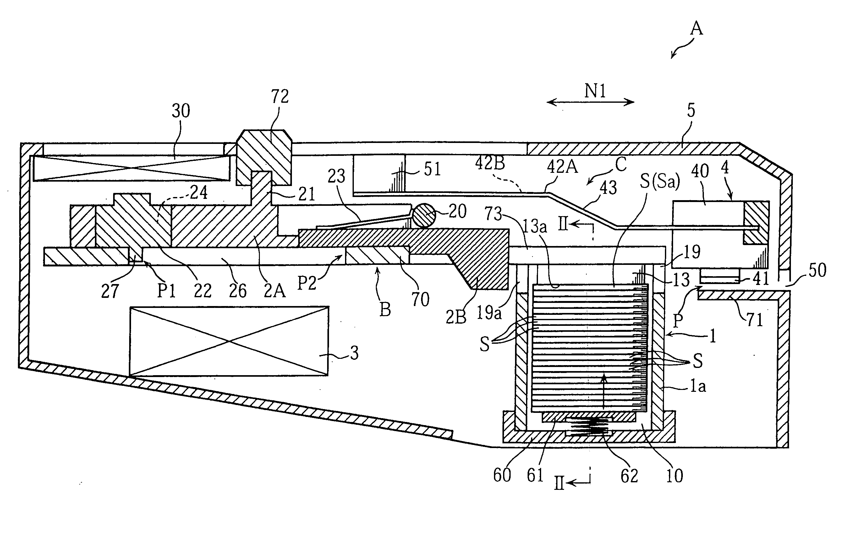
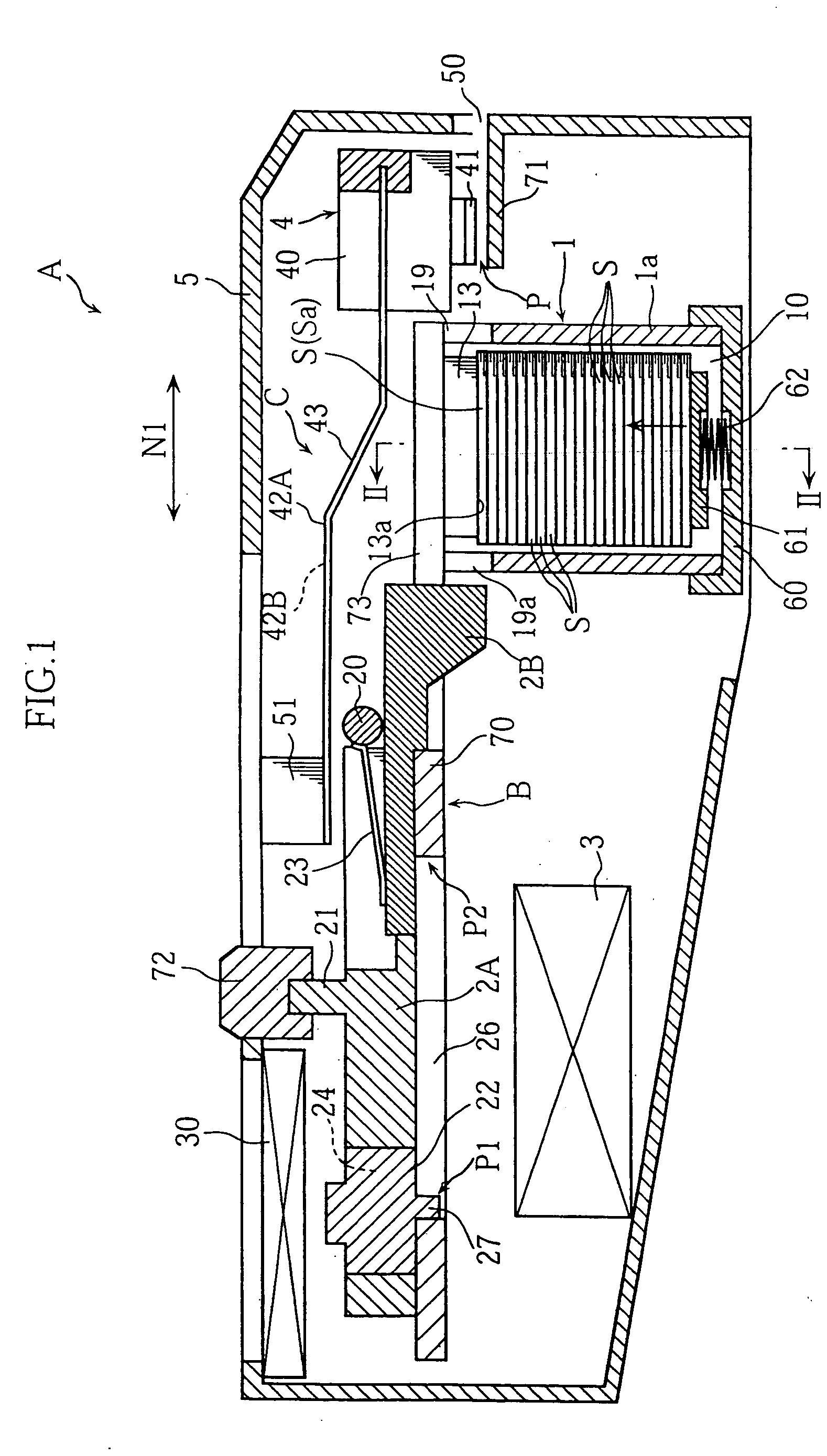
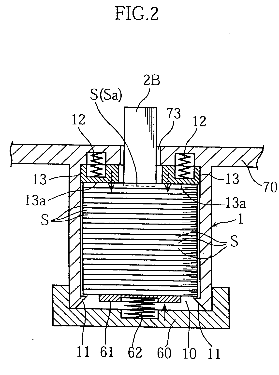
[0031]FIG. 1 and FIG. 2 show a measuring instrument according to the present invention. As clearly shown in FIG. 1, a measuring instrument A according to the present invention includes: a storage 1 for storing a plurality of sensors S; a sensor dispensing mechanism B for taking a sensor S out of the storage 1 to a predetermined measuring position P; a measurement circuit 3; a connector 4; a connector pressurizing mechanism C and a casing 5 which houses all of these. The sensor S is a small piece containing a reagent which reacts with glucose and a pair of electrodes (none of these are illustrated) contacted with the reagent.

[0032] The storage 1 is like a box, capable of storing a stack of sensors S, and has a wall 1a in the form of a rectangular tube. The wall 1a has an upper end connected to a lower surface of a base member 70 fixed in the casing 5. Th...


PUM


Abstract

A measuring instrument (A) includes a pressurizing mechanism (C) which moves at least one of a measuring article (S) and a connector (4) toward and into pressing contact with the other when the measuring article (S) is placed at a measuring position (P). This prevents improper connection between the connector (4) and the measuring article (S) caused by wear of the connector (4).

Description

TECHNICAL FIELD [0001] The present invention relates to measuring instruments and related techniques used in such an application as measuring the glucose level in human blood. BACKGROUND ART [0002] As a conventional example in the field of measuring instrument, a device is known in which a cartridge loaded with a plurality of sensors is set to a predetermined position, and an operation is made to a sensor dispensing mechanism for taking a sensor, one at a time, out of the cartridge to a predetermined measuring position (See JP-A 8-262026 for example). The sensor is, for example, a small piece containing a reagent which reacts with e.g. glucose in the blood, and provided with a pair of electrodes. Near the measuring position, a connector is provided, which makes contact with the pair of electrodes of the sensor when the sensor comes to the measuring position. With such an arrangement, when the reagent in the sensor makes contact with the blood of the user, a measurement circuit in th...

Claims


Application Information

Patent Timeline
IPC IPC(8): G01D11/24G01N33/487
CPCG01N33/48757G01D11/24
Inventor MATSUMOTO, DAISUKE
Owner ARKRAY INC
Learn More