
Equalization method and apparatus using the same
a technology of equalization and apparatus, applied in the field of equalization technology, can solve the problems of deteriorating the quality of received signals, radio transmission paths and noise power are subject to time-dependent variation, and the above-mentioned control does not necessarily achieve an improvement in the received signal quality
- Summary
- Abstract
- Description
- Claims
- Application Information
AI Technical Summary
Benefits of technology
Problems solved by technology
Method used
Image

Examples
first example
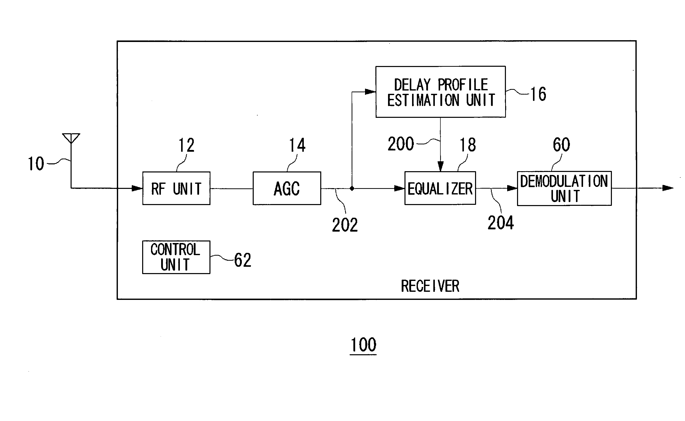
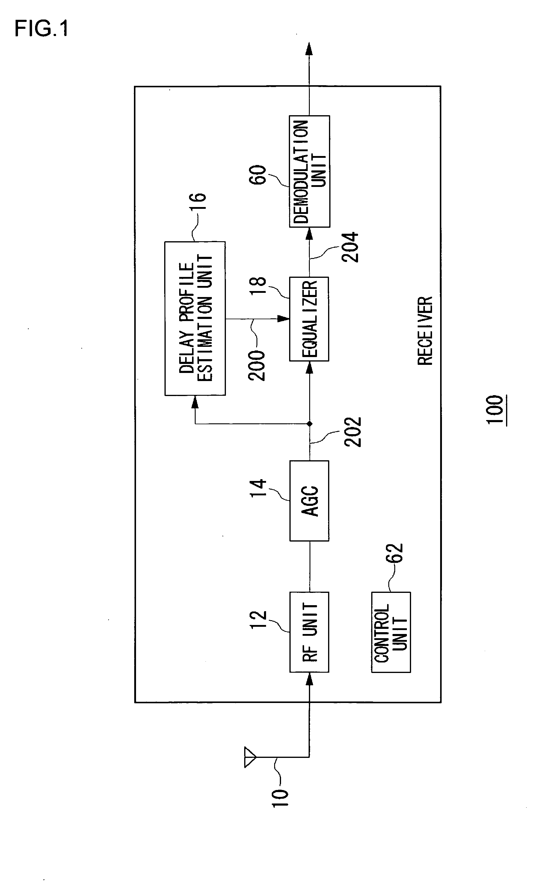
[0029] A summary of the invention will be given before giving a detailed description. A first example relates to a wireless LAN receiver according to the IEEE802.11b standard. The receiver includes a linear filter and a decision feedback equalizer (hereinafter, referred to as DFE) for an equalization process. A signal output from the linear filter is input to the DFE. The linear filter and the DFE are both constructed as an arrangement of a plurality of taps. The numbers of taps in the linear filter and the DFE are configured such that the DFE is capable of removing a delay wave of a longer propagation delay than that of the wave removed by the linear filter.
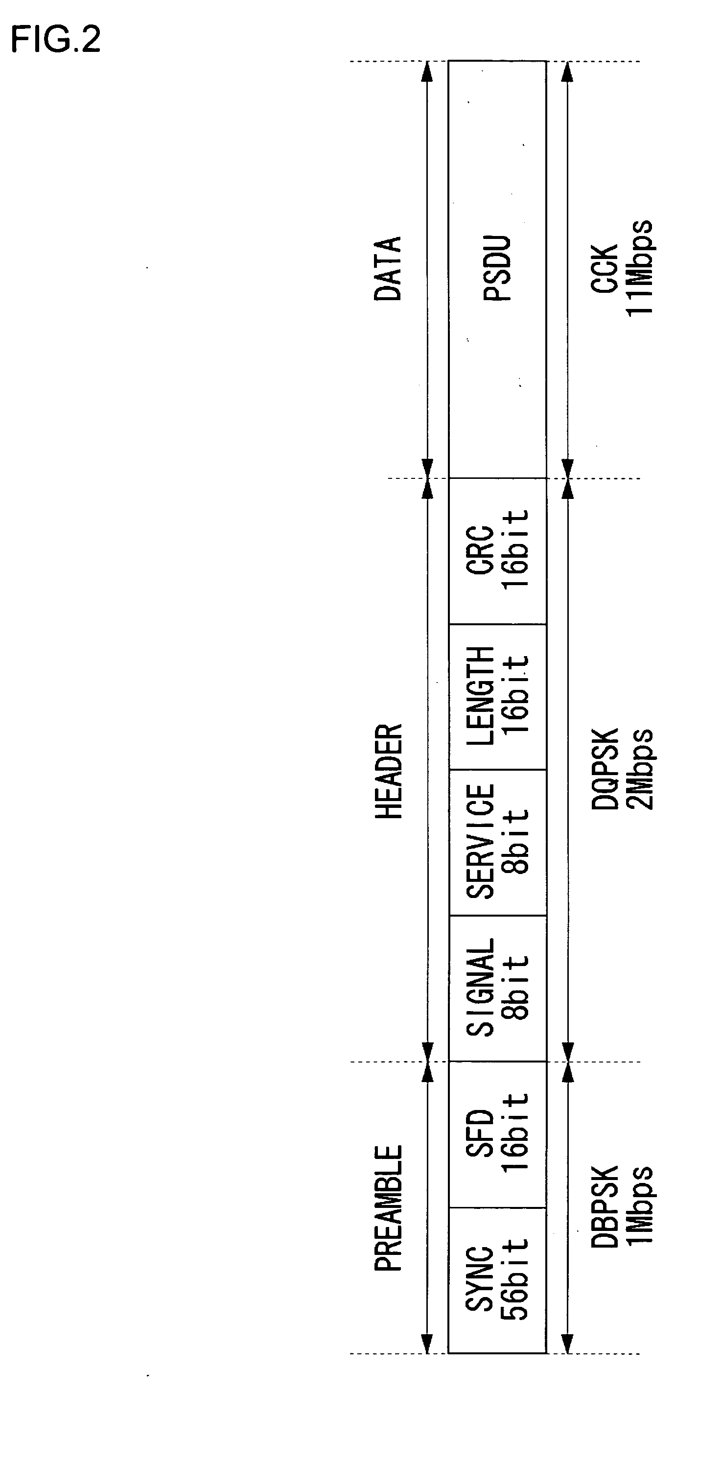
[0030] When the receiver according to this example receives a burst signal from a transmitter via a radio transmission path, the receiver identifies, by referring to the head of the burst signal, a plurality of received power levels characterized by respective propagation delays incurred in the radio transmission path. That is,...
second example
[0065] In the second example of the present invention, taps to be used in an equalization process are determined in accordance with a delay spread estimated by referring to a received signal. Unlike the first example, taps to be used are selected from a plurality of taps included in the linear filter instead of the DFE. Moreover, the threshold level used in determining the taps to be used in an equalization process is modified in accordance with the configuration of delay profile.
[0066]FIG. 7 shows a construction of the equalizer 18 according to the second example. The equalizer 18 of FIG. 7 is constructed such that the DFE unit 22 is removed from the equalizer 18 of FIG. 3. The linear filter unit according to the second example differs from the linear filter unit 20 of FIG. 5 in that there are provided a second delay unit 30b, a twenty-first delay unit 30u, a third holding unit 32c and a third multiplying unit 34c. The operation of the delay unit 30, the holding unit 32 and the mu...
PUM
 Abstract
Description
Claims
Application Information