Filter structure and method of fabrication

a filter and conductive wire technology, applied in the field of filters, can solve the problems of affecting the mounting of electronic parts, the filter is not stable, and the circuit board is occupied with more spa

Inactive Publication Date: 2005-06-02
LIN CHIA HO
View PDF4 Cites 17 Cited by
  • Summary
  • Abstract
  • Description
  • Claims
  • Application Information

AI Technical Summary

Problems solved by technology

Therefore, more space of the circuit board is occupied, and this will affect the mounting of electronic parts.
In other words, the filter is not stable.

Method used


Image

  • Filter structure and method of fabrication
  • Filter structure and method of fabrication
  • Filter structure and method of fabrication

Examples


Embodiment Construction

[0016] The following descriptions are of exemplary embodiments only, and are not intended to limit the scope, applicability or configuration of the invention in any way. Rather, the following description provides a convenient illustration for implementing exemplary embodiments of the invention. Various changes to the described embodiments may be made in the function and arrangement of the elements described without departing from the scope of the invention as set forth in the appended claims.

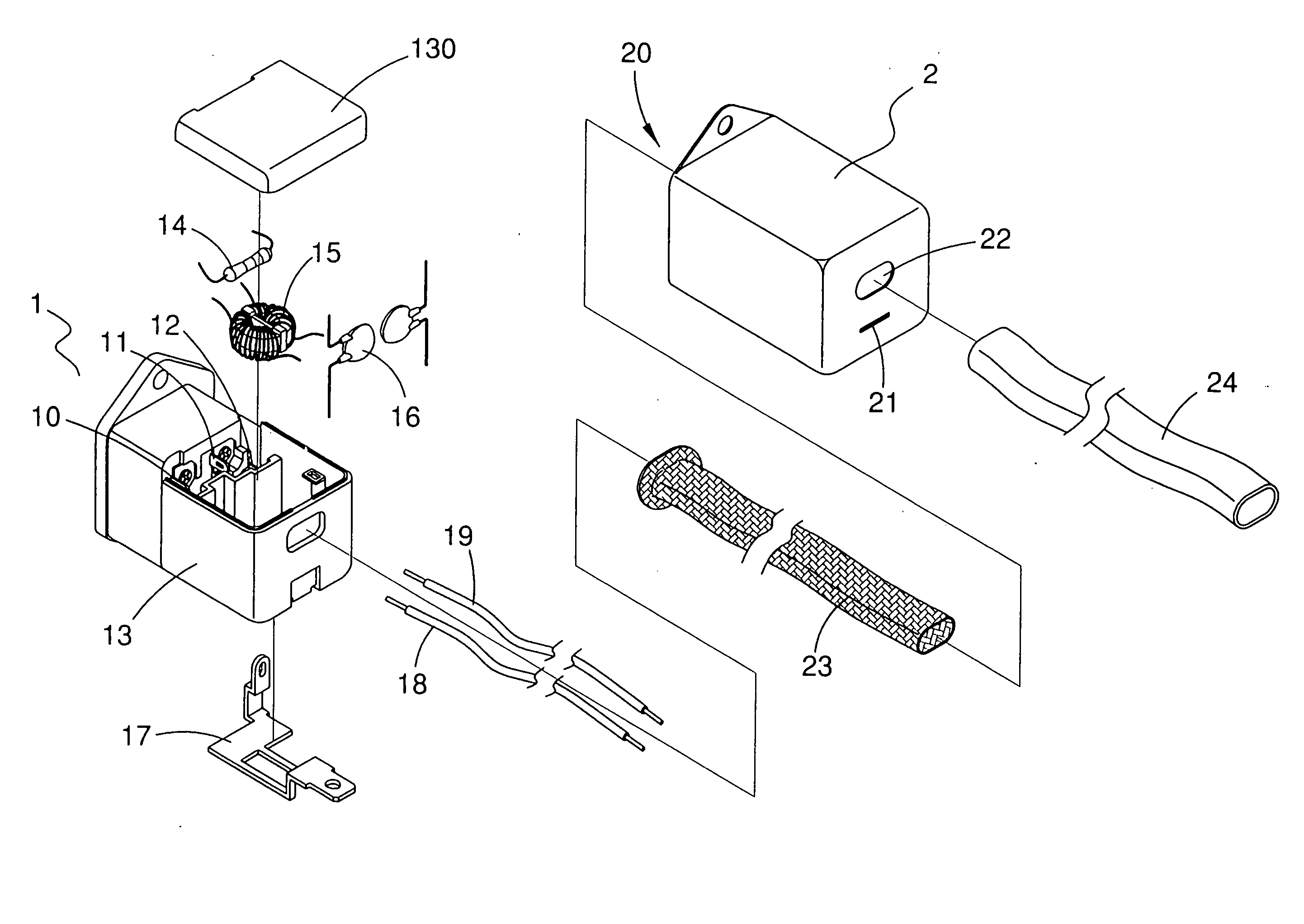
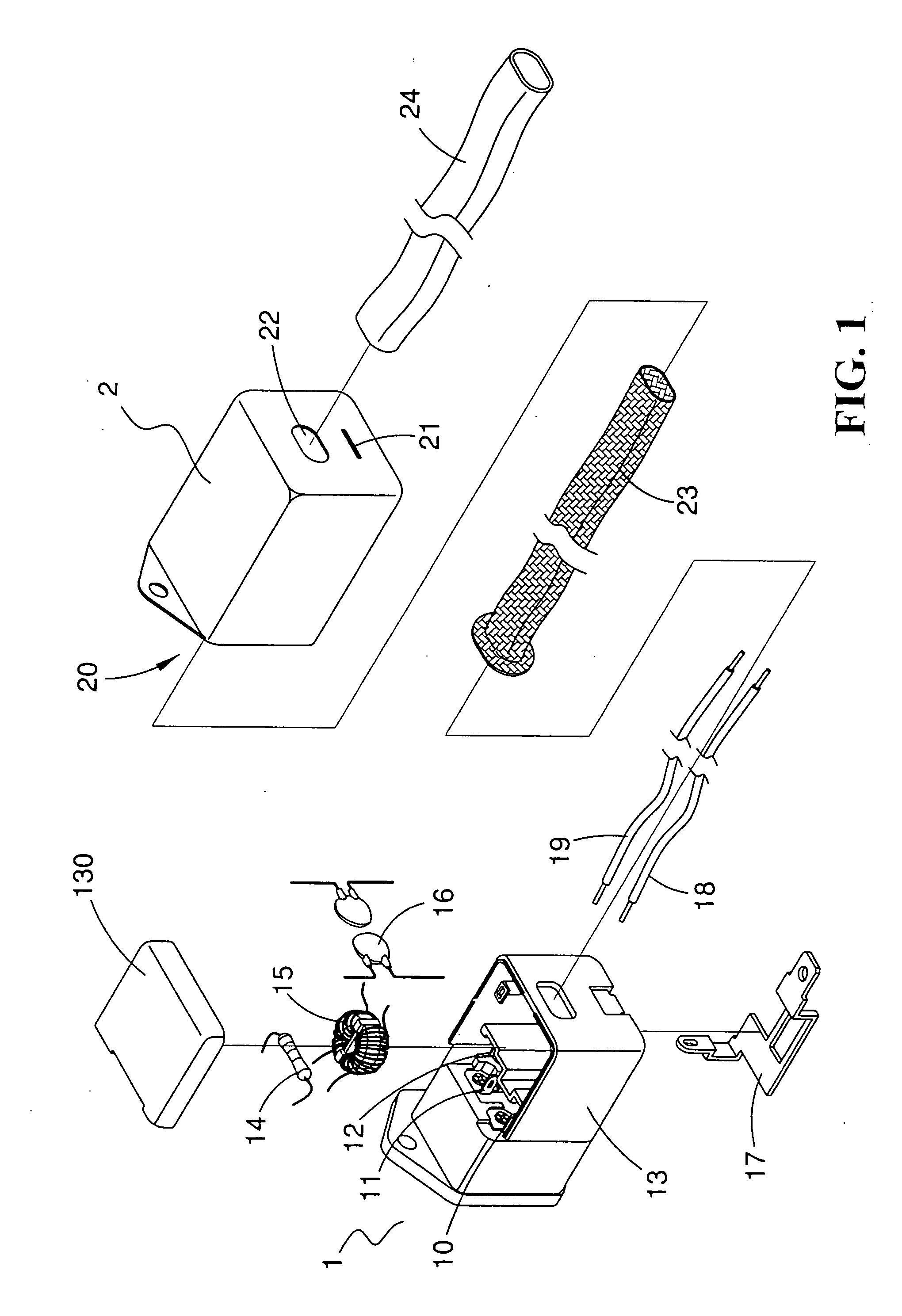
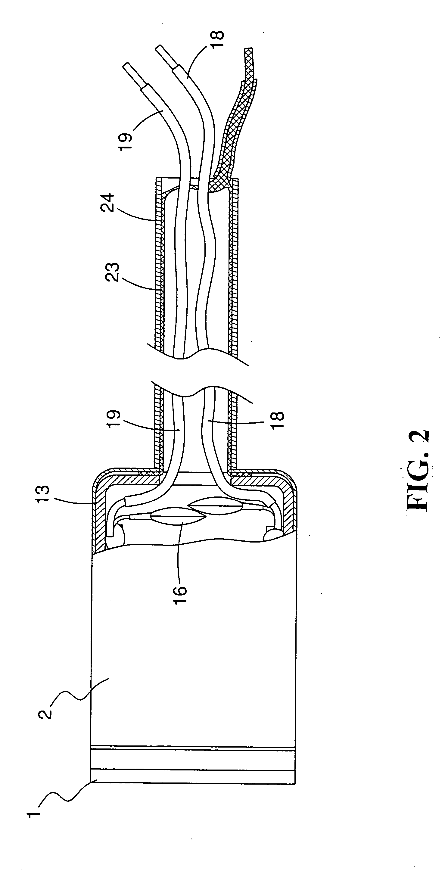
[0017] Referring to FIGS. 1 and 2, there is shown a filter structure and a method of fabrication of the filter. The filter comprises an insertion seat 1 having a positive terminal pin, a negative terminal pin and a ground terminal pin (not shown) respectively extended to another lateral side, and the lateral side being correspondingly mounted with a positive terminal pin 10, a negative terminal pin 11 and a ground terminal pin 12, and the lateral side connected to a box body 13. The box body 13...


PUM

PropertyMeasurementUnit
conductiveaaaaaaaaaa
resistanceaaaaaaaaaa
capacitanceaaaaaaaaaa

Abstract

A filter structure and the method of fabrication are disclosed. The filter comprises an insertion seat including a box body at one side thereof and a plurality of electronic modules within the box body and the external side of the box body mounted to a ground terminal, and the electronic modules and the ground terminal formed an electronic loop of the filter, and the positive and negative terminal of the electronic loop being soldered to a positive conductive wire and a negative conductive wire; and a metallic housing having an opened cavity at one side for the mounting of the insertion seat and the bottom portion of the cavity being a terminal hole and a conductive wire hole, and the conductive wire hole being extended to form an isolation mount which functions as electromagnetic wave isolation, and the external of the isolation mount being mounted with an insulated rubber mount and one end of the positive conductive wire and the negative wire from the conductive wire hole via the isolation mount to the exterior, and the ground terminal passed through the terminal hole to the exterior.

Description

BACKGROUND OF THE INVENTION [0001] (a) Technical Field of the Invention The present invention relates to a filter, and in particular, to a filter structure having conductive wire, and a method of fabricating the filter. [0002] (b) Description of the Prior Art [0003]FIG. 6 shows a conventional filter comprising an insertion seat 4 having a box body 40 at one side thereof containing resistance 41, electric induction coil 42 and Y capacitance 43 electronic modules. A cover 400 covers the box body 40 and one side of the box body 40 is provided with a positive terminal plate 44, a negative terminal plate 45 and a ground plate 46 for connecting with the electronic modules to form into an electronic loop. One side of the insertion seat 4 and the exterior of section of the box body 40 is mounted with a metallic housing 5 such that the positive terminal plate 44, the negative terminal plate 45 and the ground plate 46 are exposed externally on the metallic housing 5. [0004] The conventional f...

Claims


Application Information

Patent Timeline
Patent Type & Authority Applications(United States)
IPC IPC(8): H01F17/06H01F27/02H01F27/04H01F27/40H01R13/66H03H3/00H03H9/46H05K9/00
CPCH01F17/06H01F27/02H05K9/0066H01F27/40H01F27/04
Inventor LIN, CHIA HO
Owner LIN CHIA HO
Why Eureka
Try Eureka