
Cocking plate

Inactive Publication Date: 2005-06-09
MAY WILLIAM
View PDF16 Cites 1 Cited by
  • Summary
  • Abstract
  • Description
  • Claims
  • Application Information

AI Technical Summary

Benefits of technology

[0006] The invention offers at least one of the following advantages:
[0007] provides a support that helps stabilize a firearm such as a spear gun during the reloading process;

Problems solved by technology

A problem encountered by the underwater hunter is holding the spear gun during the reloading of the spear gun.
These bands are particularly difficult to stretch or draw, and many accidents occur as the butt of the gun slips from the stomach, or as the rubber bands slip from the hands of the diver.
Divers have come to accept the fact that reloading is a very difficult task.

Method used


Image

  • Cocking plate
  • Cocking plate
  • Cocking plate

Examples


Embodiment Construction

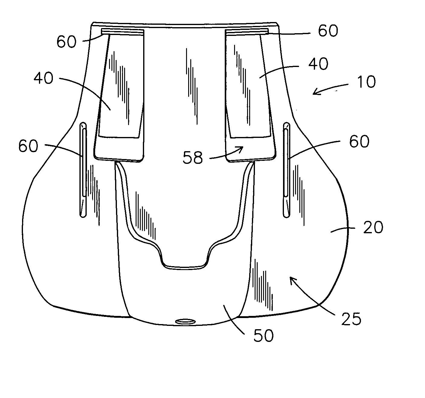
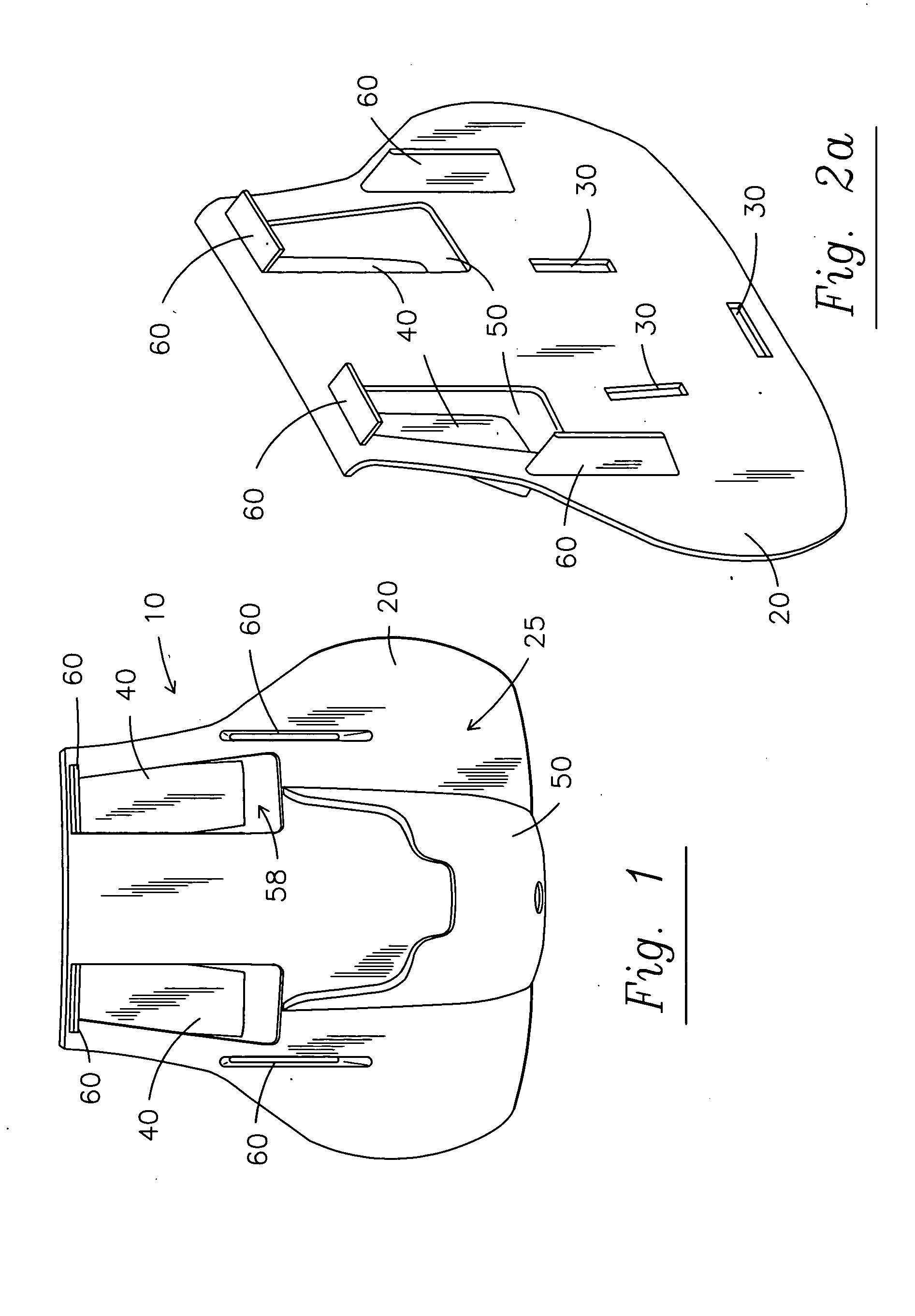
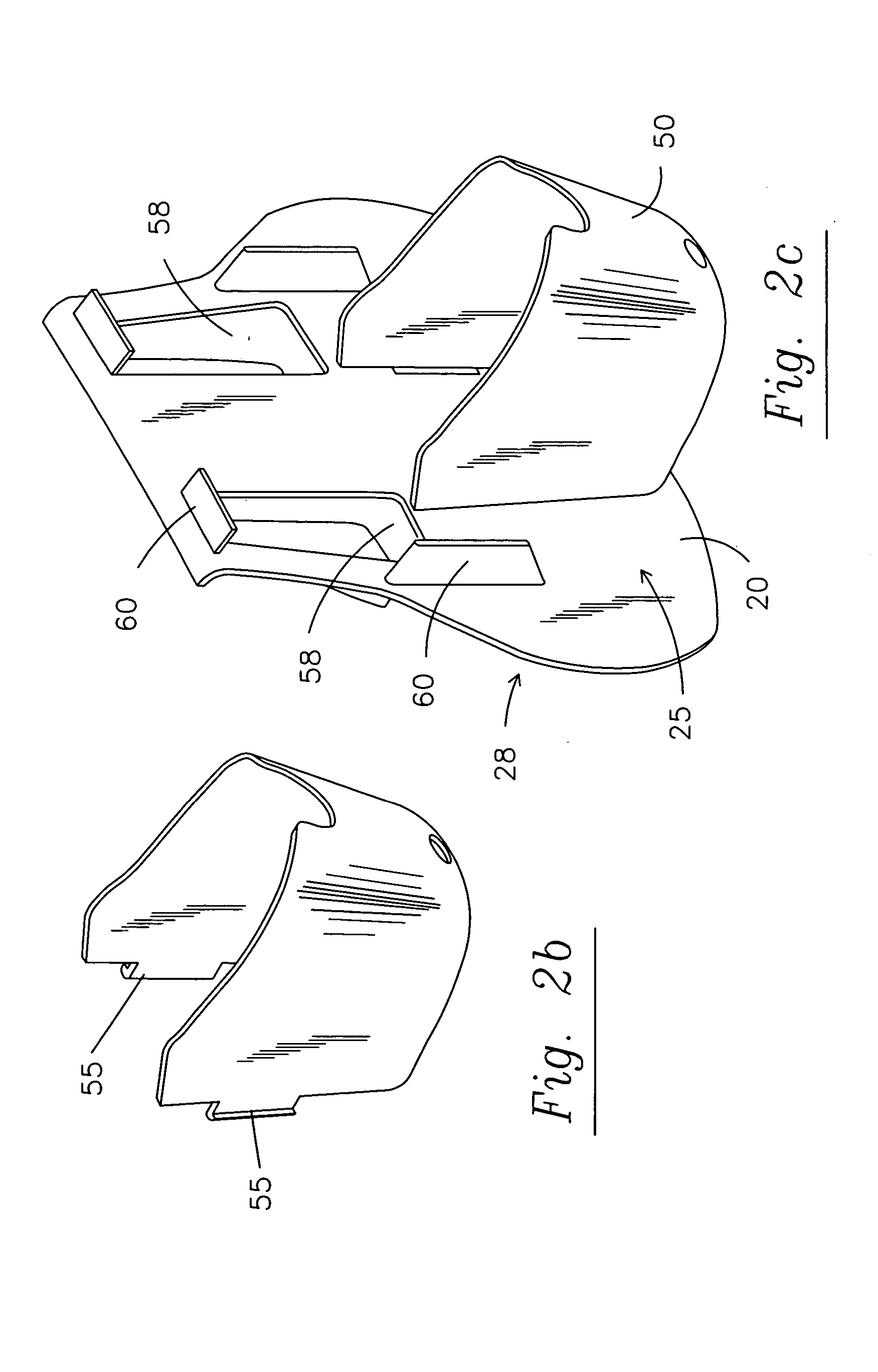
[0030] The present invention provides a quicker but firmly attachable cocking plate for the belt of a user, to which the base of an article such as a spear gun can be secured.

[0031] The cocking plate, according to the present invention, allows loading a firearm such as a spear gun more easily and with greater stability. In addition, the cocking plate prevents the slip of the firearm, thus the loading process is safe.

[0032] When using a sling spear gun, the cocking plate will allow the use of stronger bands due to this stability.

[0033]FIGS. 1-7 show the cocking plate for helping in the reloading of a spear gun according to the present invention.

[0034] The cocking plate 10 for holding the base of an article, comprising: [0035] a plate 20 having a front side 25, a back side 28, at least one slot 30 and at least one clamping means 40; and [0036] a receiving cup 50 connected to the front side 25 of the plate 20, wherein the receiving cup 50 includes connecting means 55 to connect the...


PUM


Abstract

The present invention concerns a cocking plate for holding the base of an article. The cocking plate comprises: a plate having at least one slot and at least one clamping means and a receiving cup having means for attaching to the at least one recess of the plate. The cocking plate is adapted to be used in conjunction with a belt.

Description

REFERENCE TO RELATED APPLICATIONS [0001] This application is a non-provisional of Provisional Application No. 60 / 509,616 filed Oct. 8, 2003.TECHNICAL FIELD [0002] The present invention relates to a cocking plate for holding the end of an article. More specifically, to a cocking plate that facilitates the reloading of a firearm such as a spear gun. BACKGROUND OF THE INVENTION [0003] A problem encountered by the underwater hunter is holding the spear gun during the reloading of the spear gun. Typically, the spear is inserted in the barrel of an elastic band type gun until it is seated in the trigger mechanism, and then the butt end of the gun is placed against the stomach, and the elastic bands are pulled one at a time, with both hands, from the front of the gun and stretched to the back and set in notches in the spear. [0004] Underwater hunters wanting power out of their spear gun will use thick, powerful elastic bands. These bands are particularly difficult to stretch or draw, and m...

Claims


Application Information

Patent Timeline
IPC IPC(8): F41B7/04
CPCF41B7/04A01K81/00
Inventor MAY, WILLIAM
Owner MAY WILLIAM
Learn More