Printhead maintenance station

Active Publication Date: 2005-07-21
SILVERBROOK RES PTY LTD +1
View PDF18 Cites 29 Cited by
  • Summary
  • Abstract
  • Description
  • Claims
  • Application Information

AI Technical Summary

Benefits of technology

[0131] one of the opposed wall sections is displaceable and biased to expand the variable ink storage volume to

Problems solved by technology

With such a printer unit it may be possible to remove the printhead for replacement, however the other parts of the print engine, such as the media transport rollers, control circuitry and maintenance stations, are typically fixed within the printer unit and replacement of these p

Method used


Image

  • Printhead maintenance station
  • Printhead maintenance station
  • Printhead maintenance station

Examples


Embodiment Construction

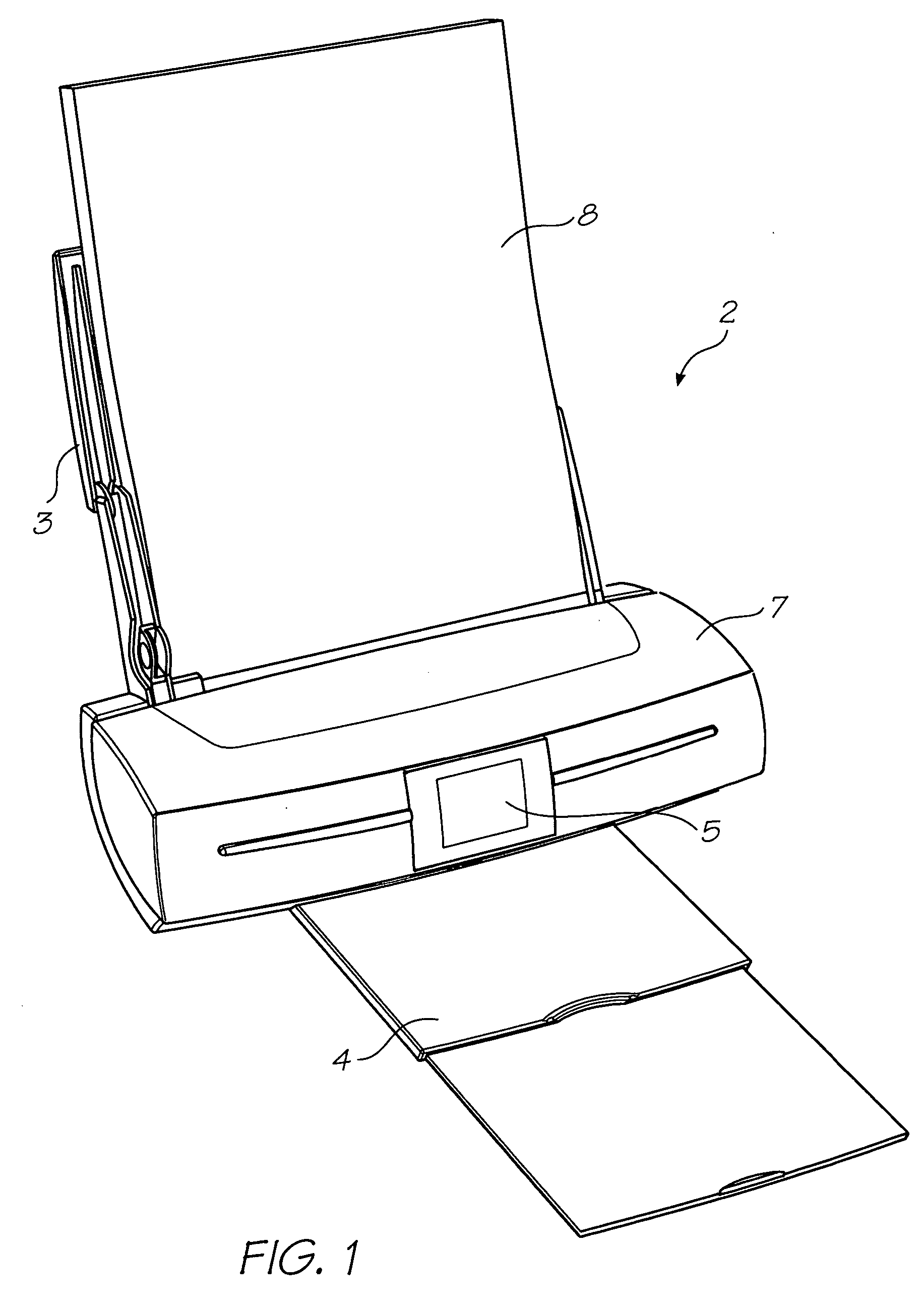
[0259]FIG. 1 shows a printer unit 2 embodying the present invention. Media supply tray 3 supports and supplies media 8 to be printed by the print engine (concealed within the printer casing). Printed sheets of media 8 are fed from the print engine to a media output tray 4 for collection. User interface 5 is an LCD touch screen and enables a user to control the operation of the printer unit 2.

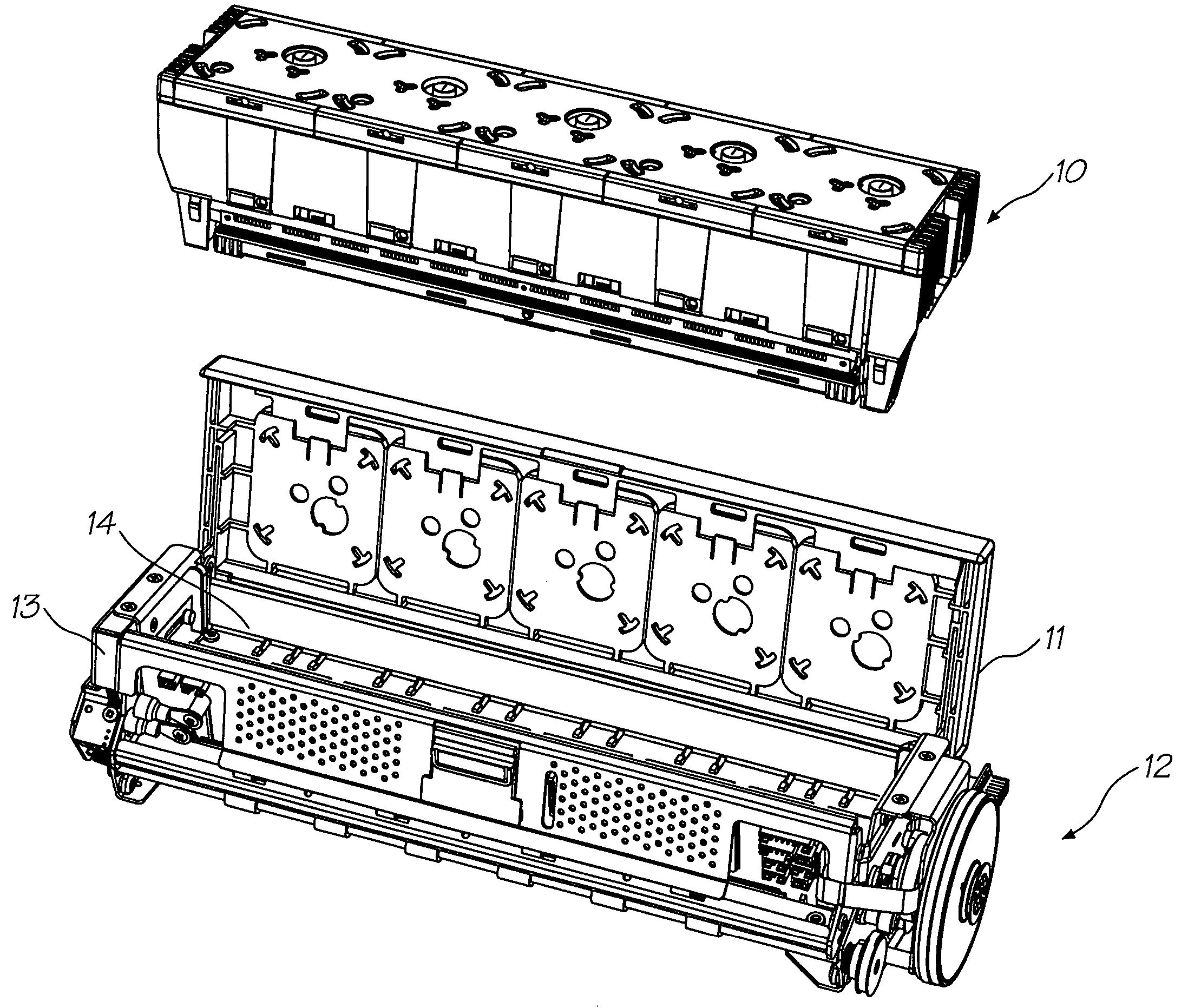
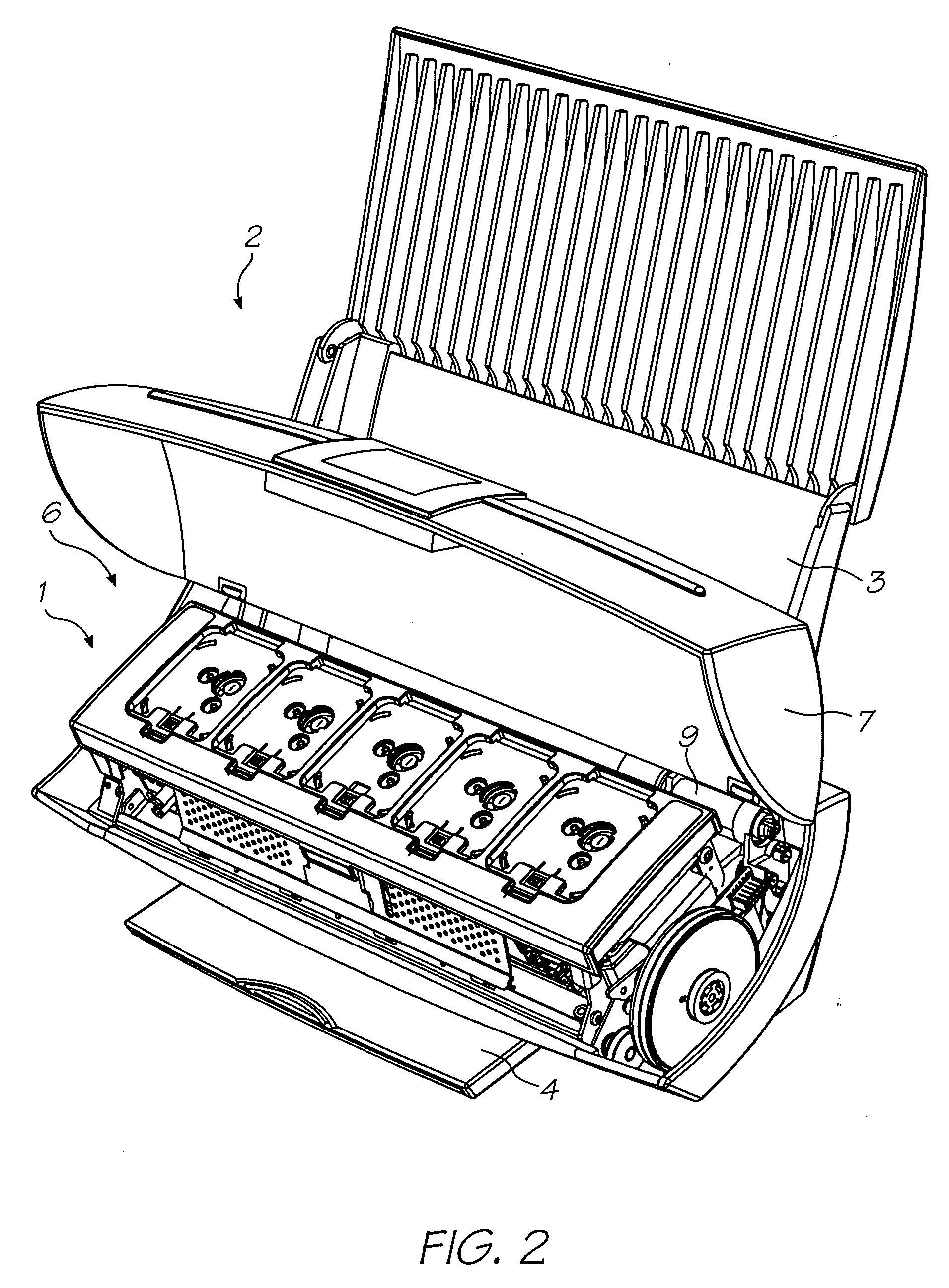
[0260]FIG. 2 shows the lid 7 of the printer unit 2 open to expose the print engine 1 positioned in the internal cavity 6. Picker mechanism 9 engages the media in the input tray 3 (not shown for clarity) and feeds individual streets to the print engine 1. The print engine 1 includes media transport means that takes the individual sheets and feeds them past a printhead assembly (described below) for printing and subsequent delivery to the media output tray 4 (shown retracted).

[0261]FIG. 3 schematically shows how the printer unit 2 is arranged to print documents received from an external source, ...


PUM


Abstract

A printhead maintenance assembly for an inkjet printhead, the printhead having a nozzle plate with an array of nozzles formed therein, the printhead maintenance assembly comprising: a capper to cover the array of nozzles when the printhead is not in use; and, a cleaner for engaging the nozzle plate and wiping across the nozzles; wherein, the cleaner is positioned between opposing sides of the capper.

Description

[0001] The present application is a Continuation-In-Part application of U.S. Ser. No. 10 / 760,254 filed on Jan. 21, 2004. In the interests of brevity, the disclosure of the parent application is incorporated in its entirety into the present specification by cross reference.FIELD OF THE INVENTION [0002] The present invention relates to printers and in particular inkjet printers. Specific aspects of the invention relate to cartridges for printers, printhead design and maintenance, as well as other facets of printer operation. CO-PENDING APPLICATIONS [0003] The following applications have been filed by the Applicant simultaneously with the present application: RRB001USRRB002USRRB003USRRB004USRRB005USRRB006USRRB007USRRB008USRRB009USRRB010USRRB011USRRB012USRRB013USRRB014USRRB015USRRB016USRRB017USRRB018USRRB019USRRB020USRRB021USRRB022USRRB023USRRB024USRRB025USRRB026USRRB027USRRB030USRRB031USRRB032USRRB033USRRC001USRRC002USRRC003USRRC004USRRC005USRRC006USRRC007USRRC008USRRC010USRRC011USRRC...

Claims


Application Information

Patent Timeline
IPC IPC(8): B41J2/175B41J29/02
CPCB41J2/04541B41J2/17503B41J2/0458B41J2/04585B41J2/04591B41J2/14016B41J2/14427B41J2/155B41J2/1623B41J2/1628B41J2/1634B41J2/1637B41J2/1642B41J2/1648B41J2/16526B41J2/16535B41J2/16585B41J2/1707B41J2/1714B41J2/175B41J2/17506B41J2/17509B41J2/17513B41J2/1752B41J2/17536B41J2/17553B41J2/17556B41J2/17566B41J2/19B41J2/515B41J29/02B41J29/13B41J29/38B41J2002/14362B41J2002/14403B41J2002/14419B41J2002/14435B41J2002/14459B41J2002/14475B41J2002/14491B41J2002/1742B41J2002/17516B41J2202/19B41J2202/20B41J2202/21B41J2/135B41J2/04543B29C64/209B41J25/34
Inventor SILVERBROOK, KIANAKAZAWA, AKIRAHIBBARD, CHRISTOPHERMACKEY, PAUL IANBERRY, NORMAN MICHEALJACKSON, GARRY RAYMOND
Owner SILVERBROOK RES PTY LTD
Why Eureka
Try Eureka