Plasma display panel drive method

Inactive Publication Date: 2005-08-04
PANASONIC CORP
View PDF5 Cites 9 Cited by
  • Summary
  • Abstract
  • Description
  • Claims
  • Application Information

AI Technical Summary

Problems solved by technology

However, in spite of display of images with high contrast, the above driving method has a probl

Method used


Image

  • Plasma display panel drive method
  • Plasma display panel drive method
  • Plasma display panel drive method

Examples


Embodiment Construction

[0020] An exemplary embodiment of the present invention is described hereinafter with reference to the accompanying drawings.

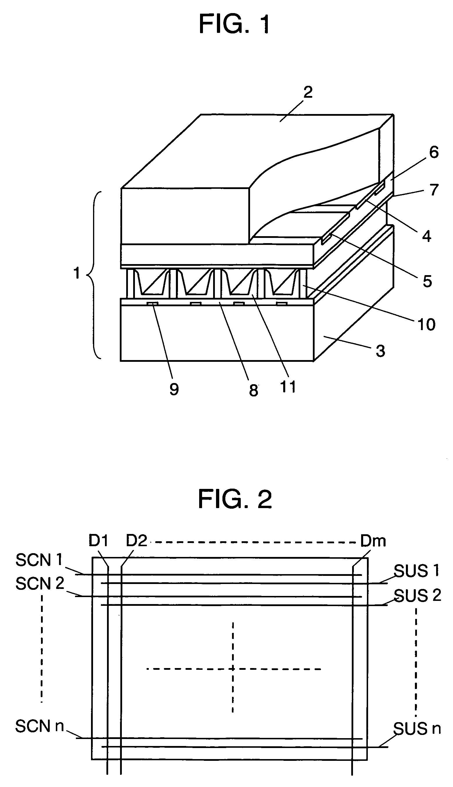
[0021]FIG. 1 is a perspective view illustrating an essential part of a plasma display panel in accordance with the exemplary embodiment of the present invention. Panel 1 is composed of front substrate 2 and rear substrate 3 that are made of glass and faced with each other so as to form a discharge space therebetween. On front substrate 2, a plurality of display electrodes, each formed of a pair of scan electrode 4 and sustain electrode 5, is formed in parallel with each other. Dielectric layer 6 is formed to cover scan electrodes 4 and sustain electrodes 5. On dielectric layer 6, protective layer 7 is formed. On the other hand, on rear substrate 3, a plurality of data electrodes 9 covered with insulating layer 8 is provided. Barrier ribs 10 are provided on insulating layer 8 between data electrodes 9 in parallel therewith. Also, phosphor 11 is provided on the...


PUM


Abstract

A method of driving a plasma display panel including discharge cells, each at an intersection of a scan electrode and a sustain electrode, and a data electrode. One field period is divided into a plurality of sub-fields, each having an initializing period, writing period, and sustaining period. The sustaining period of at least one sub-field has a first sustaining period and a second sustaining period. In the first sustaining period, a transition period of a sustain pulse applied to the scan electrode is not temporally overlapped with a transition period of a sustain pulse applied to the sustain electrode. In a second sustaining period, a transition period of the sustain pulse applied to the scan electrode is temporally overlapped with a transition period of the sustain pulse applied to the sustain electrode. The second sustaining period is included at least at the end of the sustaining period.

Description

TECNICAL FIELD [0001] The present invention relates to a method of driving a plasma display panel used as a thin display device having a large screen and light weight. BACKGROUND ART [0002] An alternating current surface-discharging panel representing a plasma display panel (hereinafter abbreviated as a panel) has a plurality of discharge cells formed between facing front panel and rear panel. In the front panel, a plurality of display electrodes, each formed of a pair of scan electrode and sustain electrode, are formed on a front glass substrate in parallel with each other. A dielectric layer and a protective layer are formed to cover these display electrodes. On the other hand, in the rear panel, a plurality of data electrodes is formed in parallel with each other on a rear glass substrate. A dielectric layer is formed on the data electrodes to cover them. Further, a plurality of barrier ribs are formed on the dielectric layer in parallel with the data electrodes. Phosphor layers ...

Claims


Application Information

Patent Timeline
IPC IPC(8): G09G3/20G09G3/288G09G3/292G09G3/294
CPCG09G3/2927G09G2360/16G09G2320/0228G09G3/294
Inventor OGAWA, KENJIKIGO, SHIGEOSASAKI, KENJI
Owner PANASONIC CORP
Why Eureka
Try Eureka