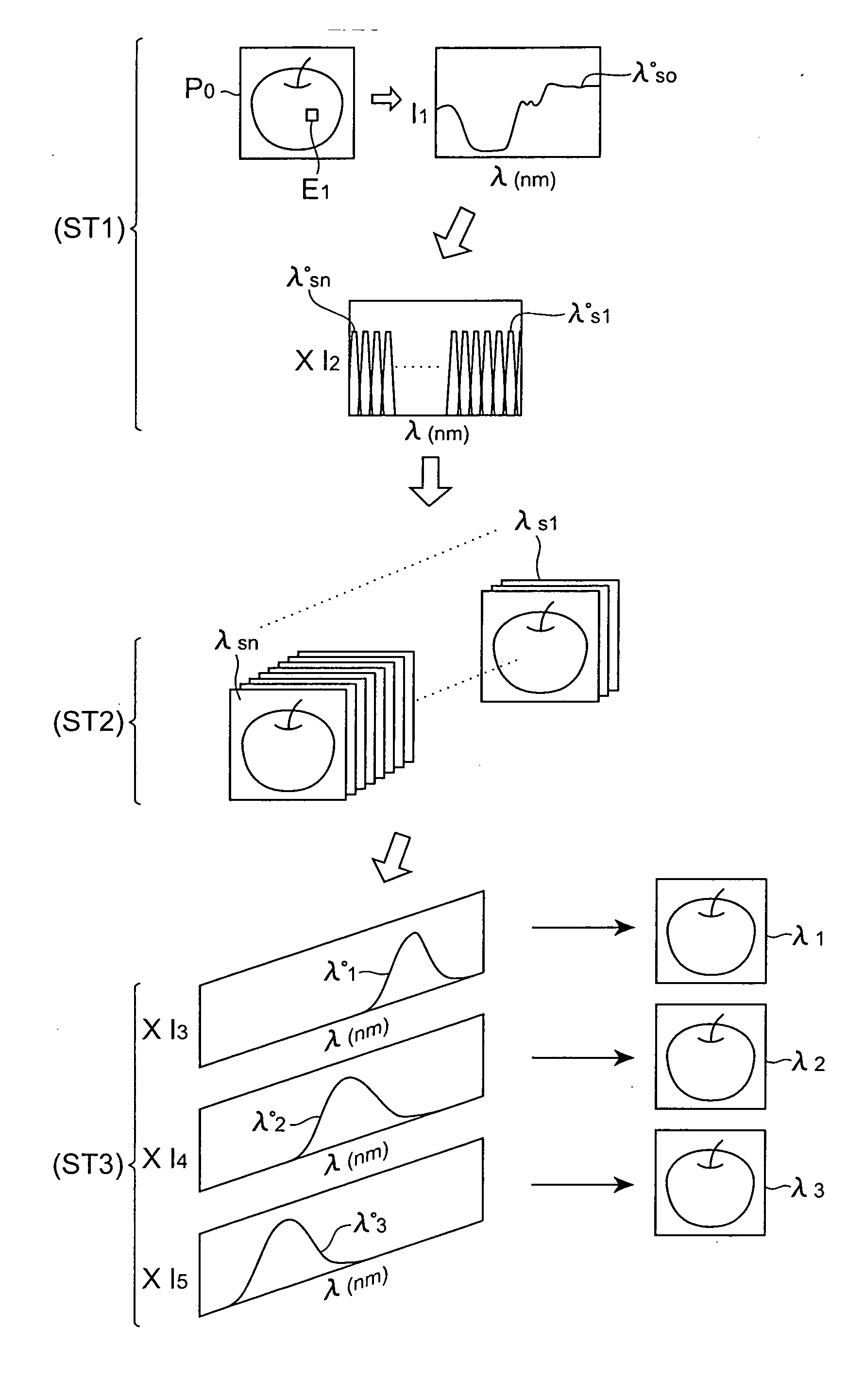
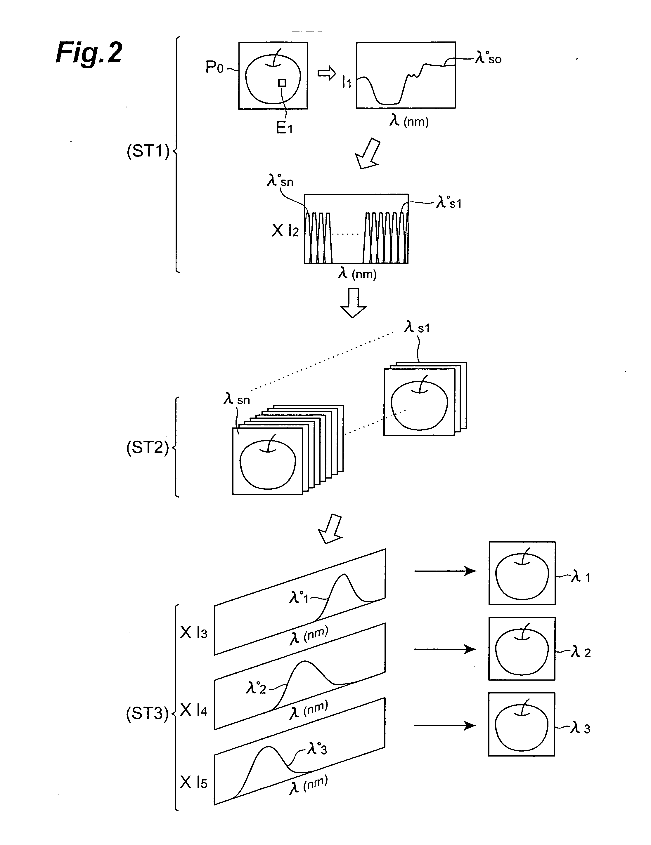
[0017] This invention has been made in view of the above problems, and an object thereof is to provide a system enabling
chromaticity measurement in the visible and invisible ranges that adequately enables the information desired to be acquired from a subject sample to be adequately evaluated quantitatively by use of color values of the invisible range and color display of a pseudo color image.
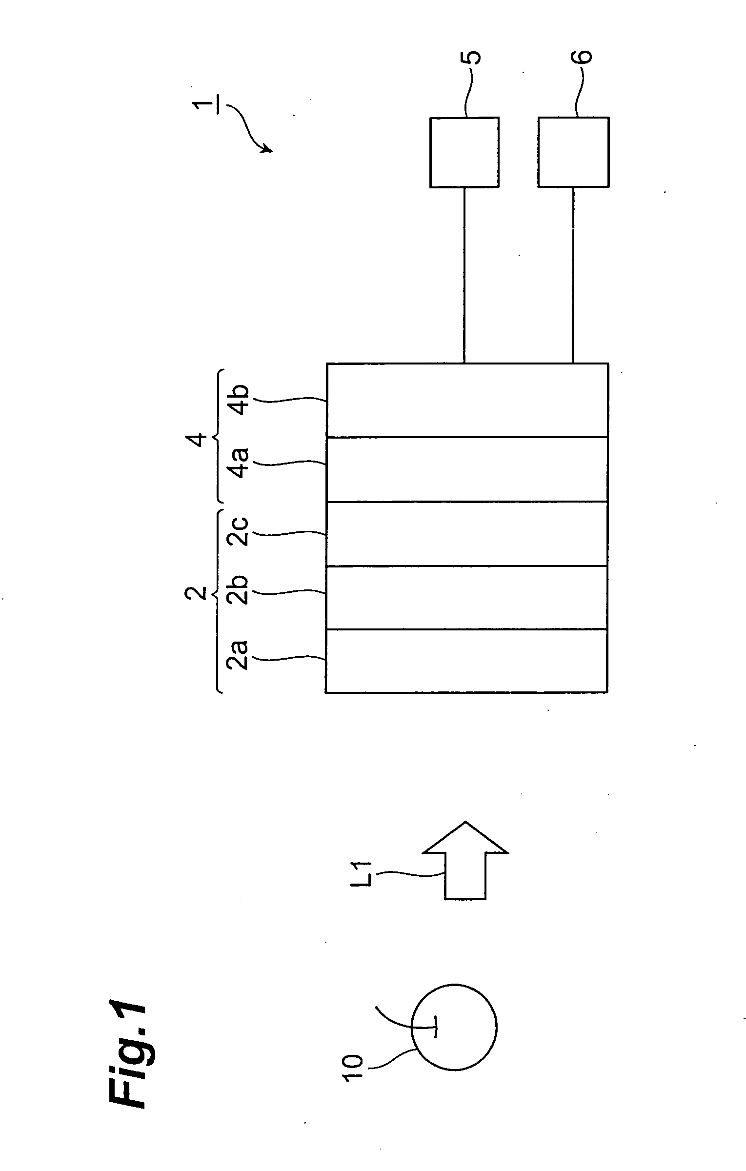
[0021] That is, this invention provides a system enabling
chromaticity measurement in the visible and invisible range, comprising at least: a spectroscopic optical part for receiving emitted light of all
wavelength ranges emitted from a subject sample and spectrally separating the above-mentioned emitted light into three or more component lights having mutually different central wavelengths; a
photoelectric conversion part for photoelectrically converting the three or more component lights, respectively, and generating three or more electric signals, respectively, corresponding to the three or more component lights; an
image processing part for
processing the three or more electric signals to generate a pseudo color image of the sample and compute a numerical value defined based on a color specification system for performing color display of the pseudo color image; and an image outputting part for outputting the pseudo color image and / or the numerical value, wherein the image
processing part comprises at least:
image signal generation
processing means for generating three or more basic pseudo color image signals by applying three or more sensitivity functions independently to all of the three or more electric signals; vector conversion processing means for generating the three or more pseudo color image signals by performing vector conversion by applying a matrix M to the three or more basic pseudo color image signals;
image formation processing means for generating the pseudo color image by synthesizing the three or more pseudo color image signals; and color specification processing means for computing the numerical value defined based on the color specification system by use of the three or more pseudo color image signals, and wherein the three or more sensitivity functions are determined based on a correlation between physical state or
chemical state differences to be observed that occur among respective subjects constituting up a subject set to which the subject sample belongs, and differences in waveform occurring among optical spectra of the respective subjects constituting the subject set. The matrix M is a matrix for approaching optimal sensitivity characteristics and is determined so that, in consequence, the
color reproduction error that is generated when generating the three or more pseudo color image signals is minimized.
[0025] The color information constituting the pseudo color image obtained finally is thus closely associated with the information desired to be acquired from the subject sample. With the present invention, since the color information of the pseudo color image obtained finally can be quantified numerically by a method used in a color specification system for carrying out color display of visible light color images, the numerically quantified color information of the pseudo color information are closely associated with the information desired to be acquired from the subject sample. Consequently, with the present invention, the information desired to be acquired from a subject sample can be adequately evaluated quantitatively using the color display of the pseudo color image.
[0026] Also, with the present invention, even in a case where pseudo color image is output separately by image outputting parts (monitors or printers) or the like, which differ in pseudo color
image display conditions and the color display states of these pseudo color images are recognized as being different in terms of color
sensation or color
perception, the information desired to be acquired from a subject sample can be ascertained accurately in the form of numerical values defined based on the color specification system.
[0027] This invention also provides a system enabling chromaticity measurement in the visible and invisible range, comprising at least: a spectroscopic optical part for receiving emitted light of all
wavelength ranges emitted from a subject sample and spectrally separating the above-mentioned emitted light into three or more component lights having mutually different central wavelengths;
wavelength conversion optical parts which are provided, respectively, for each of said three or more component lights and generates three or more pseudo color component lights corresponding to the three or more component lights respectively by performing
wavelength conversion of each of the three or more component lights and thereby optically applying sensitivity functions to each of the three or more component lights; a
photoelectric conversion part for photoelectrically converting the three or more pseudo color component lights respectively and thereby generating three or more basic pseudo color image signals respectively corresponding to the three or more pseudo color component lights; an image processing part for processing the three or more basic pseudo color image signals to generate a pseudo color image of the sample and calculate a numerical value defined based on a color specification system for performing color display of the pseudo color image; and image outputting part for outputting the pseudo color image and / or the numerical value, wherein the image processing part comprises at least: vector conversion processing means for generating the three or more pseudo color image signals by performing vector conversion by applying a matrix M to the three or more basic pseudo color image signals;
image formation processing means for generating the pseudo color image by synthesizing the three or more pseudo color image signals; and color specification processing means for calculating the numerical value defined based on the color specification system by use of the three or more pseudo color images, and wherein the three or more sensitivity functions are determined based on a correlation between physical state or
chemical state differences to be observed that occur among respective subjects constituting a subject set to which the subject sample belongs, and differences in waveform occurring among optical spectra of the respective subjects constituting the subject set, and the matrix M is a matrix for approaching optimal sensitivity characteristic and is determined so that, in consequence, the
color reproduction error that is generated when generating the three or more pseudo color image signals is minimized.

