
Method and device for recognizing an illuminated roadway ahead of a vehicle

Active Publication Date: 2014-11-27
ROBERT BOSCH GMBH
View PDF3 Cites 9 Cited by
  • Summary
  • Abstract
  • Description
  • Claims
  • Application Information

AI Technical Summary

Benefits of technology

This patent is about a method for controlling the headlights of a vehicle to avoid blinding other road users. By using a minimum number of road illumination units and recognizing them from a vehicle, the method allows for a continuous illumination of the roadway. The headlights can then be adjusted accordingly to optimize visibility without compromising safety. The technical effect is improved safety for drivers and other road users.

Problems solved by technology

However, this requires a high scanning rate of the optical sensor for recognizing roadway illumination units of this type, which is only possible using a small image sensor.
This approach is problematic not only due to the high scanning rate for camera systems, but also due to the increase in clocked light sources in automobiles.
Another option is to use map / navigation system information that indicates where a city begins; however, map material quickly becomes outdated for technical reasons.
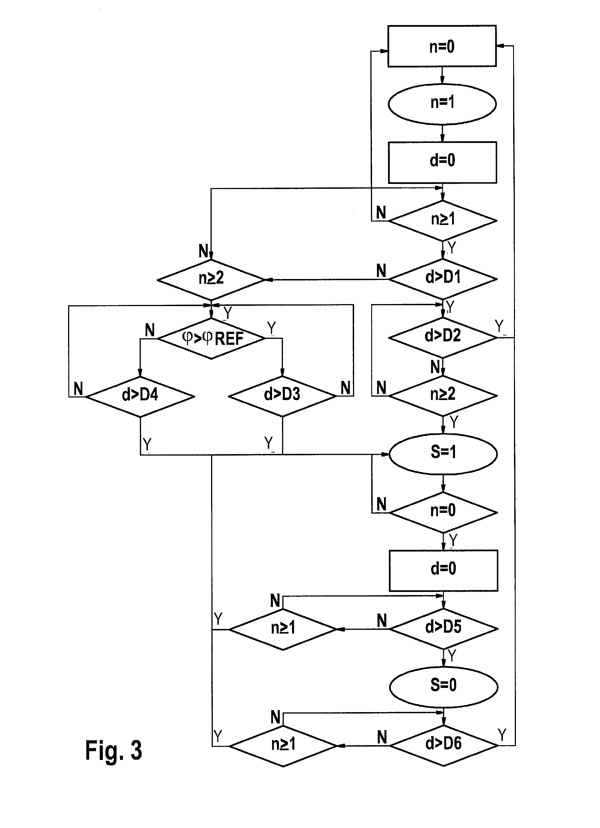
This means that when the light is switched back to the original illumination characteristic too early, a longer period should be awaited the next time, since the overall distance from the roadway illumination unit may possibly be very large, or many obscurations are present.

Method used


Image

  • Method and device for recognizing an illuminated roadway ahead of a vehicle
  • Method and device for recognizing an illuminated roadway ahead of a vehicle
  • Method and device for recognizing an illuminated roadway ahead of a vehicle

Examples


Embodiment Construction

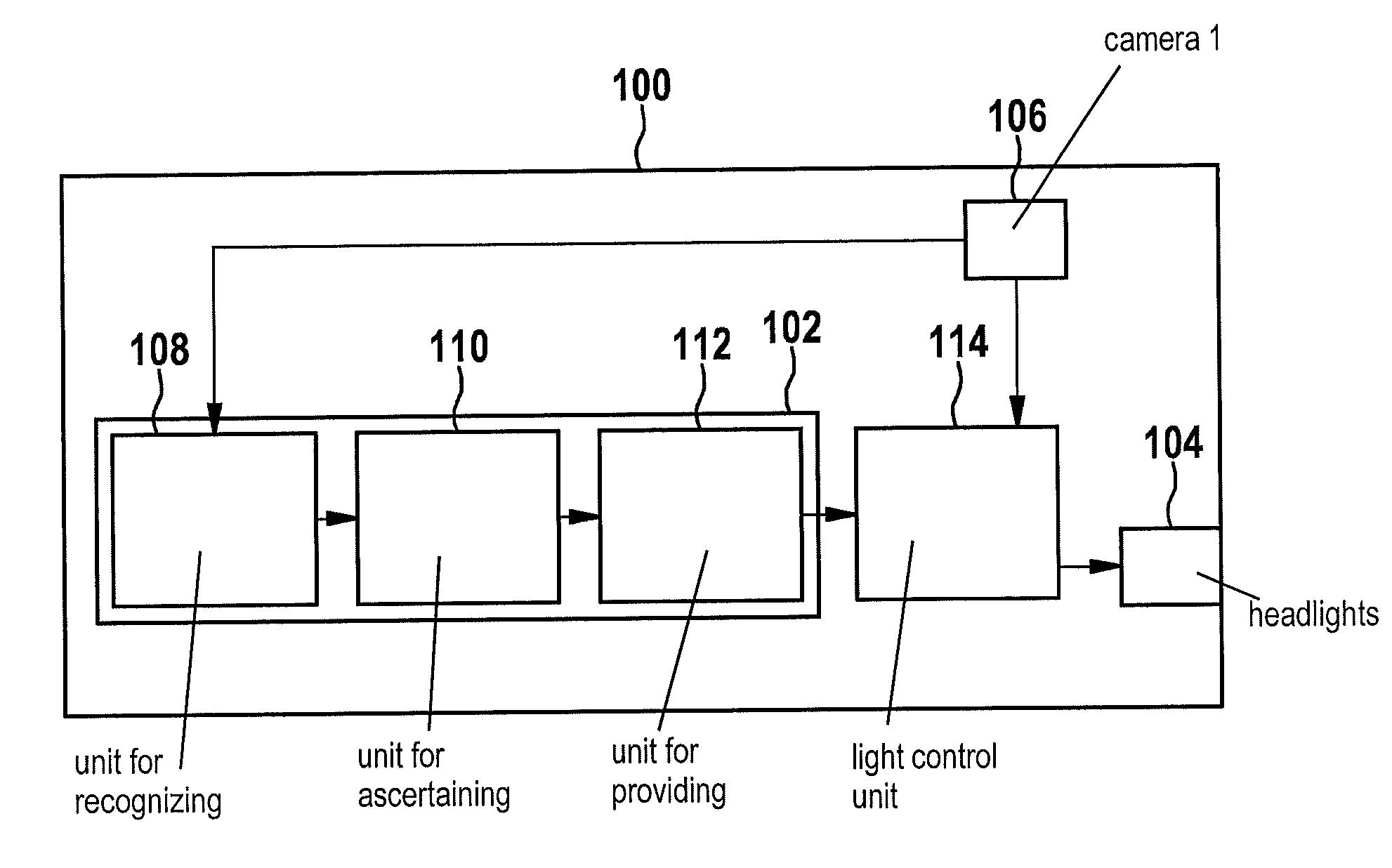
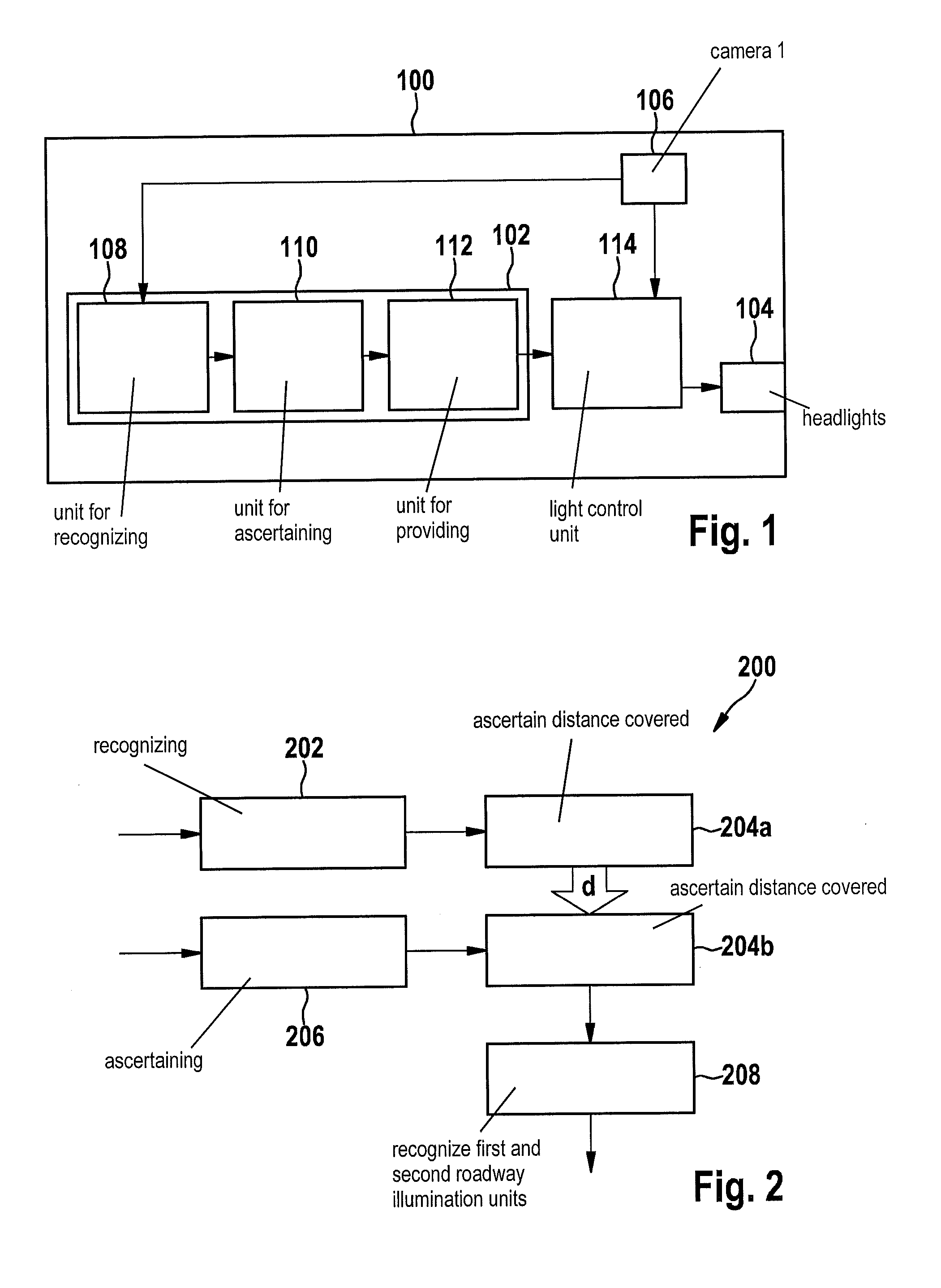
[0037]In the following description of preferred exemplary embodiments of the present invention, identical or similar reference numerals are used for the elements having a similar action which are illustrated in the various figures, and a repeated description of these elements is dispensed with.

[0038]A recognition of continuous roadway illumination is also important when other high-beam assistant systems such as adaptive high-beam control (AHBC), which is related to the sliding headlight range control, or a glare-free high beam are to be used, since these systems may also be regarded as high-beam light distribution. The vehicle detection in darkness (VDD) algorithm recognizes streetlamps in the image, which may be utilized to recognize continuous roadway illumination.

[0039]A simple assumption that a “continuous roadway illumination signal” (with appropriate switchover to low beam or a special light distribution for city light) is generated as soon as roadway illumination has been rec...


PUM


Abstract

A method for recognizing an illuminated roadway ahead of a vehicle, having a step of recognizing a first light object as a first roadway illumination unit. The method also includes a step of ascertaining a distance covered by the vehicle. The method also includes a step of recognizing a second light object as a second roadway illumination unit. The method also includes a step of providing a signal when the first roadway illumination unit and the second illumination unit have been recognized. The signal is provided using the distance covered, the signal representing a recognition of an illuminated roadway ahead of a vehicle.

Description

FIELD[0001]The present invention relates to a method for recognizing an illuminated roadway ahead of a vehicle, a device for recognizing an illuminated roadway ahead of a vehicle, and a corresponding computer program product.BACKGROUND INFORMATION[0002]Under European law, switching on the high beam in continuously illuminated areas is prohibited. When received light has an alternating current (AC) component or a certain frequency component, it may be concluded that roadway illumination is present. However, this requires a high scanning rate of the optical sensor for recognizing roadway illumination units of this type, which is only possible using a small image sensor. This approach is problematic not only due to the high scanning rate for camera systems, but also due to the increase in clocked light sources in automobiles. For example, LEDs are controlled by pulse-width modulation (PWM). “Chopping” and transforming, or clocking of the voltage, for example, may be used for stabilizin...

Claims


Application Information

Patent Timeline
IPC IPC(8): B60Q1/14G06K9/00
CPCB60Q1/143G06K9/00798B60Q2300/134B60Q2300/112B60Q2300/3321G06V20/584G06V20/588
Inventor FOLTIN, JOHANNES
Owner ROBERT BOSCH GMBH
Learn More