Vehicle headlamp system and dimming-type vehicle headlamp

a headlamp system and vehicle technology, applied in the direction of lighting and heating equipment, transportation and packaging, lighting support devices, etc., can solve the problems of driver uncertainty, driver uncertainty, driver uncertainty, etc., and achieve the effect of reducing uncertainty and degree of uncertainty

Inactive Publication Date: 2006-09-26
KOITO MFG CO LTD
View PDF16 Cites 8 Cited by
  • Summary
  • Abstract
  • Description
  • Claims
  • Application Information

AI Technical Summary

Benefits of technology

[0046]However, the heating value (temperature) of the filament changes according to the type of valve. Hence, variations exist in the transition point (transition temperature). The temperature distribution of the filament in the illumination valve is not constant longitudinally; rather, the temperature is high in the center of the filament and lower at both ends of the same. The effective value (about 14 volts) of the light source applied voltage used in the illumination test that was performed is higher than the effective value (about 13.0 volts) of the light source applied voltage achieved when the lamp is actually used. Further, the blinking frequency of the lamp is also high. Thus, the effective value is too rigorous to satisfy practical requirements. In consideration of the foregoing points, the “threshold value” of the effective value of the light source applied voltage is set to a value (e.g., about 9 volts) falling within the range of about 7 volts to about 9 volts, so that the life of the valve required in an actual operating state of the lamp can be ensured without fail.
[0047]To set the “threshold value” of the effective value of the light source applied voltage, a voltages witching illumination test is performed to accurately ascertain an applied voltage corresponding to the transition point (transition temperature). If the applied voltage has nominally exceeded the applied voltage, the degree of uncertainty, which would arise at final extinction of the lamp, will be preferably reduced. However, when the applied voltage approaches the effective value of the light source applied voltage corresponding to the transition point (transition temperature), the filament may be correspondingly affected by the influence of “annealing operation achieved at the transition point (transition temperature)” (i.e., an influence on a crystalline structure). Hence, the threshold value is desirably set in consideration of the uncertainty, which would arise at the time of final extinction, and safety for the required life of the valve.
[0048]Additionally, in accordance with the above described vehicle head lamp systems, dimming control performed by the dimming control means at the time of extinction is configured to lower the effective value of the light source applied voltage to a threshold value along the locus of a convex-shaped continuous hyperbola.
[0049]When dimming control has been performed through PWM (pulse width modulation) based on both a preset time and table data pertaining to a light source applied voltage, a duty ratio of PWM (i.e., a ratio of an ON time) may be linearly decreased from about 100% through duty control based on a time / applied voltage characteristic pattern in which the effective value of the applied voltage decreases with time. However, if the effective value of the light source applied voltage is controlled so as to decrease along the locus of an upwardly-convex-shaped hyperbola, the degree of decrease in the quantity of light will become larger as the effective value approaches the threshold value, thereby diminishing uncertainty which would arise when about 0 volt is achieved after the threshold value has been reached.

Problems solved by technology

The related art vehicle headlamp system having a fixed configuration of the respective low and high light distribution patterns encounters difficulty in emitting a beam in an appropriate light distribution pattern in accordance with driving conditions.
Therefore, there arises a problem of the chance of the driver feeling uncertainty due to a sudden drop in the driver's view field, or the chance of drivers of oncoming vehicles or pedestrians feeling uncertainty (e.g., a false recognition of occurrence of passing operation).
Therefore, there also arises a problem of poor appearance of the lamp.
However, such a configuration induces a related art problem of deformation of a filament of the valve (i.e., the halogen valve) of the auxiliary lamp unit to be dimmed, thereby shortening the life of the valve.
Particularly, the lower the dimming speed (i.e., the longer the filament is cooled), the greater the deformation of the filament, and the shorter the life of the valve.
Some of the adjacent coil sections contacted each other, thereby causing pitch touch.
Due to electromagnetic force generated by a rush current flowing during illumination of the valve and the thermal stress caused by a temperature variation, the filament axially expanded and contracted (i.e., vibrated) and was subjected to repetition of axial expansion and contraction, thereby resulting in deformation.
One possible reason for this effect is that the mechanical strength of a portion of the filament has become weak: that apart of the filament having low strength is deformed by expansion and contraction of the coil and that coil sections c1, c1 adjoining to the deformed area come into contact with each other, thereby causing pitch touch and rupture.

Method used


Image

  • Vehicle headlamp system and dimming-type vehicle headlamp
  • Vehicle headlamp system and dimming-type vehicle headlamp
  • Vehicle headlamp system and dimming-type vehicle headlamp

Examples


first embodiment

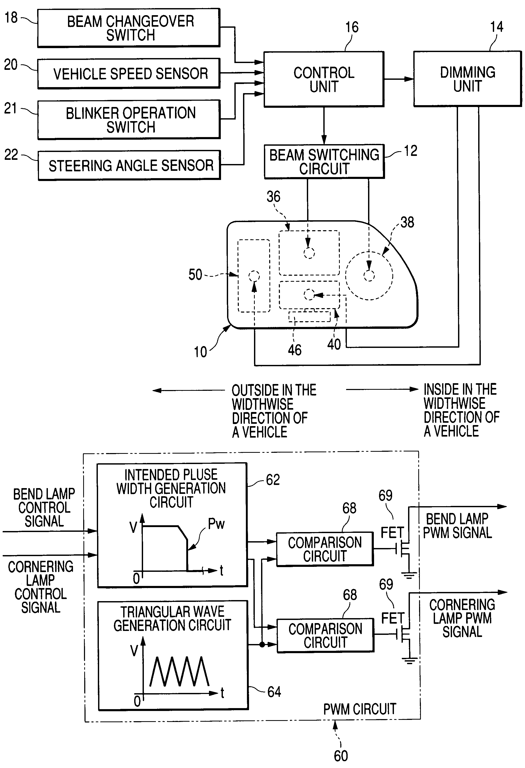
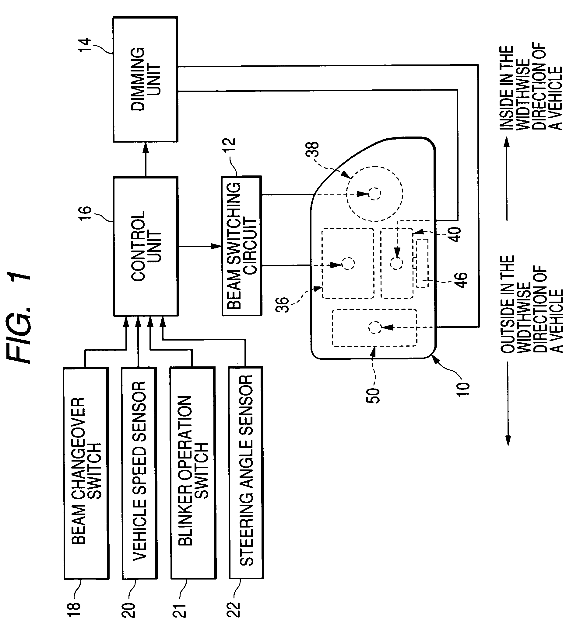
[0103]In addition to having the configuration of the first embodiment, the headlamp system is configured such that a light quantity sensor (environment illumination detection sensor) 23 is mounted on the upper surface of the dash board facing the windshield. In accordance with a signal output from the light quantity sensor 23, the valve 36b of the sub-beam formation lamp unit 36 of the headlamp is automatically illuminated or extinguished. The headlamp system is also configured so as to illuminate or extinguish the lamp units 40, 50A through use of a signal output from the light quantity sensor 23.

[0104]Specifically, the control unit 16 is configured to receive an output from the light quantity sensor 23. When the output from the light quantity sensor 23 is higher than a value (i.e., when the environment illumination is higher than the value), the environment is sufficiently bright. When the headlamp sub-beam formation lamp unit 36 is being illuminated, the lamp unit is extinguished...

second embodiment

[0106]As shown in FIG. 6, in the first exemplary, non-limiting embodiment, the light source applied voltage control pattern Pw achieved at the time of extinction is configured such that the light source applied voltage decreases linearly from the rated voltage Va to the “threshold value” Vc. As shown in FIG. 8, in the exemplary, non-limiting second embodiment, the light source applied voltage is configured to decrease to trace the locus of an upwardly-convex-shaped continuous hyperbola from the rated voltage Va to the “threshold value” Vc over a period of one second. Uncertainty which would arise after the “threshold value” has reached 0 volts is reduced.

[0107]In other respects, the second exemplary, non-limiting embodiment is identical with the first embodiment, and hence repeated explanations thereof are omitted, and like reference numerals are assigned to like features.

[0108]In the first and second embodiments, dimming control is performed such that the quantity of light is dimin...


PUM


Abstract

Lamp units for radiating a beam ahead of a vehicle in a light distribution pattern are housed in a lamp body. Illumination of the auxiliary lamp units is controlled based on driving conditions. Illumination control means extinguish light through dimming by gradually decreasing voltage applied to the light sources. When the applied voltage has dropped to a threshold value, the applied voltage is controlled to zero immediately. Compared to when the lamps remaining in an illuminated state are suddenly extinguished, a change in quantity of light is mild, and no uncertainty arises. Below a threshold value where the applied voltage gradually drops to the threshold value and a change may arise in the filament crystalline structure due to annealing at a transition temperature, the applied voltage approaches zero. Hence, the filament does not pass from the transition temperature while being rapidly cooled, thus avoiding filament crystalline structure change.

Description

[0001]The present application claims foreign priority from Japanese Patent Application No. 2003-067568, filed Mar. 13, 2003, the contents of which are incorporated herein by reference.BACKGROUND OF THE INVENTION[0002]1. Technical Field[0003]The present invention relates to a multiple-light-type vehicle headlamp system including a headlamp, the headlamp being constructed of a plurality of lamp units housed in a lamp chamber, or a headlamp formed from one or more lamp units housed in a lamp chamber as well as from an auxiliary lamp disposed in the vicinity of the headlamp. More specifically, the present invention relates to a vehicle headlamp system constructed such that the quantity of light emitted ahead of a vehicle is controlled by subjecting the quantity of light radiated from at least one lamp unit to dimming control in the former case in accordance with the driving conditions, or by subjecting the quantity of light radiated from at least one lamp unit and / or the auxiliary lamp ...

Claims


Application Information

Patent Timeline
Patent Type & Authority Patents(United States)
IPC IPC(8): B60Q1/02B60Q1/08B60Q1/12B60Q1/14B60Q1/18
CPCB60Q1/085B60Q1/12B60Q1/143B60Q1/18B60Q2300/142B60Q2300/112B60Q2300/122B60Q2300/128B60Q2300/054
Inventor NUMAJIRI, YASUYOSHIKATO, KENYOTORIYAMA, SHIGEYOSHIFUKAWA, KIYOTAKAOKAWA, MASAO
Owner KOITO MFG CO LTD
Why Eureka
Try Eureka