Image forming apparatus and liquid control method

a technology of liquid control method and image forming apparatus, which is applied in the direction of printing apparatus, inking apparatus, other printing apparatus, etc., can solve the problems of discharge abnormalities, discharge abnormalities, and significant loss of pressure applied to ink, so as to prevent discharge abnormalities and suppress the occurrence of air bubbles

Inactive Publication Date: 2008-08-26
FUJIFILM CORP
View PDF14 Cites 12 Cited by
  • Summary
  • Abstract
  • Description
  • Claims
  • Application Information

AI Technical Summary

Benefits of technology

[0016]According to the present invention, since a dissolved gas amount estimating device is provided which estimates the amount of dissolved gas contained in the liquid inside the recording head and since restoration processing of the liquid inside the recording head is carried out on the basis of the estimation results from the dissolved gas amount estimating device, it is possible to prevent discharge abnormalities caused by air bubbles forming in the ink inside the recording head, and hence a desirable discharge operation can be performed.
[0017]Furthermore, it is not necessary to provide a measuring device (dissolved oxygen meter, or the like) for measuring the amount of dissolved gas, and consequently, the device can be made more compact.
[0025]Since the amount of dissolved gas in the liquid in the vicinity of the recording head can be measured by the dissolved gas amount measuring device, it is possible to determine abnormalities in the liquid restoring device, and it is also possible to ascertain the amount of dissolved gas in the liquid, accurately. Furthermore, the dissolved gas amount measuring device may include a dissolved oxygen meter for measuring the amount of oxygen dissolved in the liquid.
[0030]The deaerating device is preferably disposed on the upstream side of the recording head with respect to the flow of the liquid, in order to carry out deaeration processing of the liquid supplied to the recording head. Furthermore, desirably, the distance between the deaerating device and the recording head is shortened.
[0039]Preferably, the image forming apparatus further comprises: a recording head temperature adjusting device which adjusts a maintenance temperature of the recording head; and a recording head temperature adjustment control device which implements control in such a manner that the maintenance temperature of the recording head is lowered using the recording head temperature adjustment device, if the estimated value has approached the reference value. According to this, since control is implemented in such a manner that the maintenance temperature of the recording head is lowered before the amount of dissolved gas in the liquid inside the recording head reaches the reference value, then it is possible to suppress the occurrence of air bubbles in the liquid inside the recording head.
[0042]According to the present invention, a dissolved gas amount estimating device is provided which estimates the amount of dissolved gas contained in the liquid inside the recording head, and if the estimated amount of dissolved gas exceeds a prescribed reference value, then restoration processing of the liquid, such as deaeration processing or purging, is carried out with respect to the liquid inside the recording head. Consequently, the amount of dissolved gas in the liquid inside the recording head is controlled in such a manner that it becomes equal to or less than the reference value, and therefore, it is possible to suppress the occurrence of air bubbles in the liquid inside the recording head and to prevent discharge abnormalities caused by the occurrence of air bubbles.

Problems solved by technology

In an inkjet printer, if air bubbles become mixed into the ink inside the recording head, then there is significant loss of the pressure applied to the ink by the actuator, and this can lead to discharge abnormalities, such as abnormalities in the amount of ink discharged or the direction of discharge, discharge failures, and the like.
Discharge abnormalities of this kind affect image recording and consequently cause a marked decline in the resulting image quality.
However, if a deaerator and a dissolved oxygen meter for measuring the amount of dissolved gas in the ink are disposed in this sequence before a print head, from the upstream side of the ink flow path, then since there is no device for measuring the dissolved gas downstream of the dissolved oxygen meter, a problem arises in that the amount of dissolved gas in the ink inside the print head will remain as it is.
Moreover, this patent publication does not provide any description relating to a multiple head in which a plurality of print heads are disposed.
For example, if a deaerator is provided at one point of an ink supply path (in other words, before branching of the path), then it may not be possible to judge conditions accurately, due to differences in the use duty of the respective print heads.
On the other hand, if deaerators are positioned after branching in a multiple head, and a dissolved oxygen meter is positioned downstream of the print heads on the circulation side, then the number of deaerators will increase and costs will rise.
Furthermore, in the inkjet printer and deaeration method for an inkjet printer according to Japanese Patent Application Publication No. 11-20194, and the inkjet recording apparatus according to Japanese Patent Application Publication No. 11-48491, a measuring device, such as a dissolved oxygen meter, for measuring the amount of dissolved gas in the ink is not provided, and therefore it is not possible to ascertain the amount of dissolved gas in the ink inside the apparatus.

Method used


Image

  • Image forming apparatus and liquid control method
  • Image forming apparatus and liquid control method
  • Image forming apparatus and liquid control method

Examples


first embodiment

[0116]Next, the ink control method and deaeration process control in an inkjet recording apparatus 10 according to a first embodiment of the present invention will be described.

[0117]Generally, in an inkjet recording apparatus, there is significant loss in the pressure applied to the ink if air bubbles become mixed into the ink chamber unit 53 illustrated in FIGS. 3A to 3C and FIG. 4, and this can give rise to discharge abnormalities.

[0118]Discharge abnormalities of this kind give rise to image deterioration, such as streaking or color irregularities, in the printed image, and thus cause a marked decline in printing quality. Therefore, in order to prevent image deterioration of this kind, deaerated ink may be used in such a manner that the amount of dissolved gas in the ink is equal to or less than a specified value.

[0119]The inkjet recording apparatus 10 is composed in such a manner that the amount of dissolved gas in the ink inside the print head 50 is estimated and deaeration pro...

second embodiment

[0159]Next, the ink control method and deaeration process control in an inkjet recording apparatus 10 according to a second embodiment of the present invention will be described.

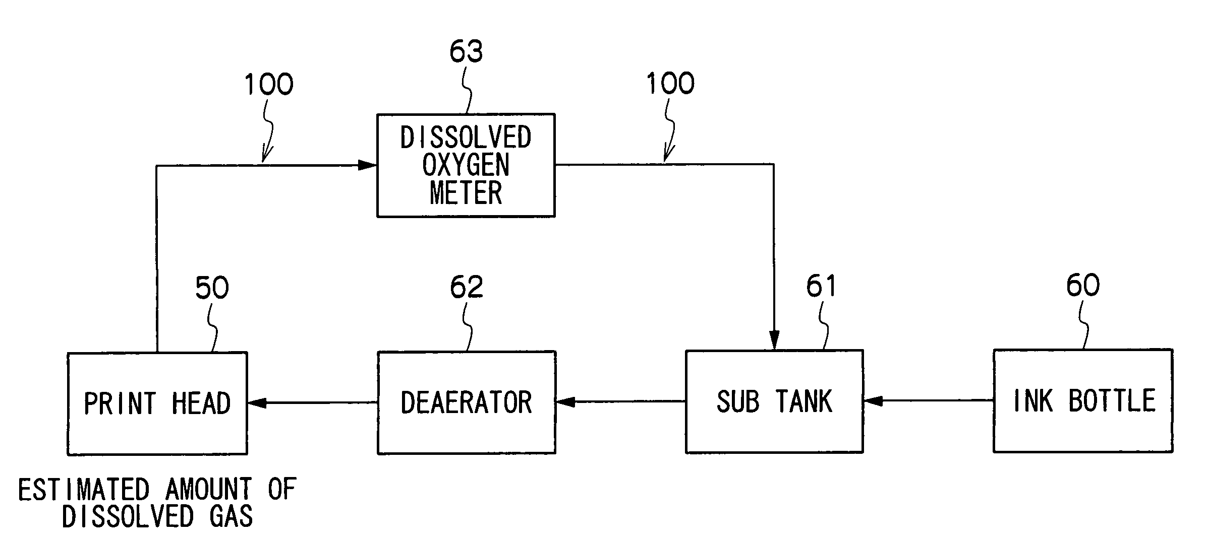
[0160]FIG. 12 shows the general configuration of the ink supply system of an inkjet recording apparatus 10 relating to the second embodiment. In FIG. 12, items which are the same as or similar to those in FIG. 8 are labeled with the same reference numerals and description thereof is omitted here.

[0161]As shown in FIG. 12, the ink supply system comprises an ink bottle 60, sub tank 61, deaerator 62, dissolved oxygen meter 63 and print head 50, disposed in this order from the upstream side of the ink flow path. In other words, compared to the ink supply system shown in FIG. 8, the dissolved oxygen meter 63 is positioned on the upstream side of the print head 50, and the circulation channel 100 is omitted.

[0162]FIG. 13 is a flowchart showing the sequence of deaeration control in an inkjet recording apparatus 10 ...


PUM


Abstract

The image forming apparatus comprises: a recording head which discharges droplets of liquid onto a recording medium; a dissolved gas amount estimating device which estimates an amount of dissolved gas contained in the liquid inside the recording head; and a liquid restoring device which carries out restoration processing of the liquid inside the recording head, if an estimated value of the amount of the dissolved gas estimated by the dissolved gas amount estimating device exceeds a prescribed reference value.

Description

BACKGROUND OF THE INVENTION[0001]1. Field of the Invention[0002]The present invention relates to an image forming apparatus and a liquid control method, and more particularly, to a liquid droplet control technology for controlling the amount of dissolved gas in liquid droplets used to form an image on a recording medium, and maintaining the liquid droplets in a desirable state.[0003]2. Description of the Related Art[0004]In recent years, inkjet printers have come to be used widely as data output apparatuses for outputting images, documents, or the like. An inkjet printer forms data on recording paper by driving recording elements (nozzles) of a recording head in accordance with data, thereby causing ink to be discharged from the nozzles. Discharge devices for causing discharge of the ink include devices using PZT actuators, or the like, which apply a pressure wave to a pressure chamber connected to a nozzle, and devices using a heat source which heats ink contained in an ink chamber...

Claims


Application Information

Patent Timeline
Patent Type & Authority Patents(United States)
IPC IPC(8): B41J2/19B41J2/045
CPCB41J2/04508B41J2/0458B41J2/04581B41J2/175B41J2/195B41J2/17596B41J2202/21B41J2002/14459B41J2202/07B41J2202/20
Inventor KOJIMA, TOSHIYA
Owner FUJIFILM CORP
Why Eureka
Try Eureka