
Liquid dispensing container with multi-position valve and straw

a liquid dispensing container and valve technology, applied in the field of liquid dispensing containers, can solve the problems of inconvenient drinking from a conventional squeeze-type container, inconvenient drinking from a squeeze-type container, so as to increase the potential use and functionality of the container, and facilitate drinking through the straw

Active Publication Date: 2017-07-04
RUNWAY BLUE LLC
View PDF44 Cites 68 Cited by
  • Summary
  • Abstract
  • Description
  • Claims
  • Application Information

AI Technical Summary

Benefits of technology

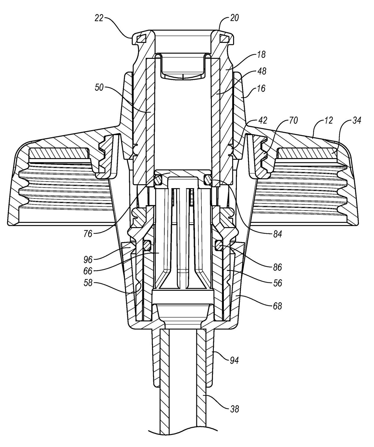
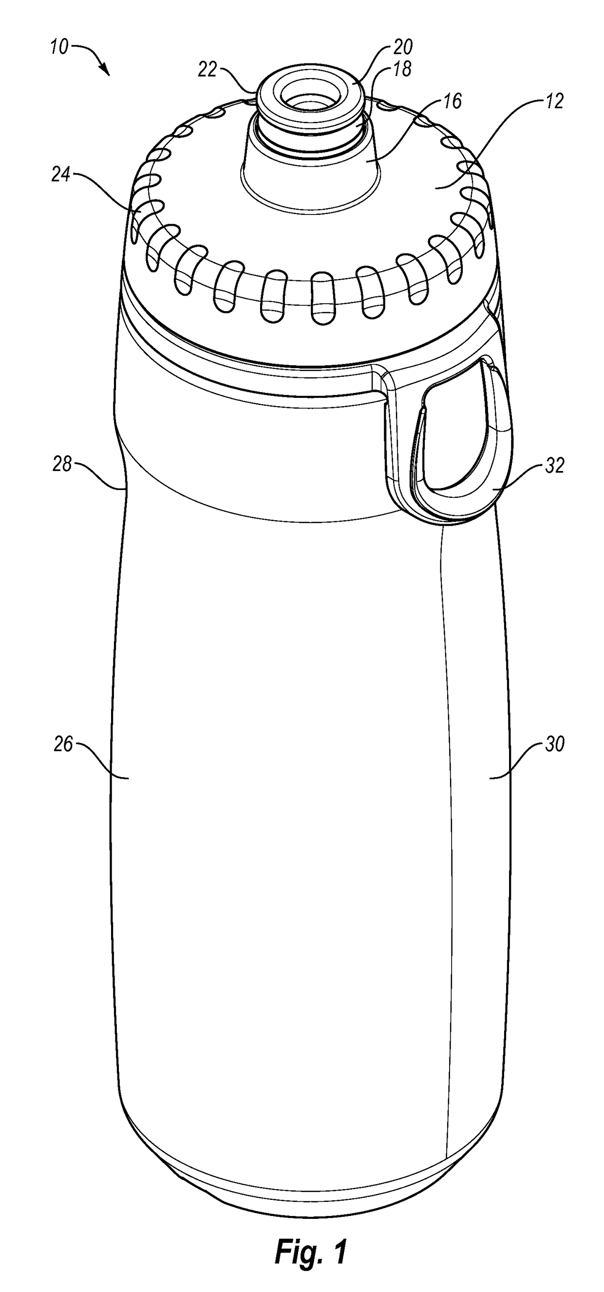
The patent text describes a liquid dispensing container with a valve assembly that can be opened in three different ways to allow fluid to be discharged from the container. The valve assembly can prevent fluid from being discharged when it is in the closed position, and can allow fluid to be discharged by inverting and / or squeezing the container when it is in the first open position. The valve assembly can also allow fluid to be discharged by sucking and / or squeezing through a straw when it is in the second open position. The valve assembly can only allow fluid to flow through one of the three passageways, depending on its position. This design solves the problems and disadvantages associated with previous liquid dispensing containers.

Problems solved by technology

In some situations, squeeze-type containers requiring inversion of the bottle for dispensing the liquid can be undesirable.
Also, a squeeze-type container, with its inherent requirement of container elevation, can be undesired in some situations.
For example, in circumstances where height or space may be limited, or where concealment is desired, it may be difficult or undesirable to invert the bottle and / or position the person's head for drinking from a conventional squeeze-type container.
This process may be time-consuming, require physical dexterity, and many times the straw may be lost before it is used.
In addition, many straw-equipped containers may allow the contents to spill or leak through the opening and / or the straw, especially when the container is full.
Also, some known straw-equipped containers only allow the contents of the container to be consumed through the straw, unless the straw is physically removed from the container.
Physical removal of the straw, however, may undesirably take a significant amount of time.
Additionally, it may be especially difficult to consume all or the last contents of many straw-equipped containers, which may waste some of the contents and the remaining contents may disadvantageously leak from the container.
Further, fast, high-volume consumption of the liquid, which may be desired during or after sports activities, can be difficult, especially when the contents of the container are low.

Method used


Image

  • Liquid dispensing container with multi-position valve and straw
  • Liquid dispensing container with multi-position valve and straw
  • Liquid dispensing container with multi-position valve and straw

Examples


Embodiment Construction

[0037]The present invention is generally directed towards liquid dispensing containers. The principles of the present invention, however, are not limited to liquid dispensing containers. It will be understood that, in light of the present disclosure, the liquid dispensing containers disclosed herein may have a variety of suitable shapes, sizes, configurations, and arrangements. It will also be understood that the liquid dispensing containers can include any suitable number of parts and components, such as containers, valve assemblies, lids, straws, and the like; and the liquid dispensing containers may include any appropriate number and combination of features, parts, aspects, and the like. In addition, while the liquid dispensing containers are illustrated in the accompanying figures as having particular styles and configurations, it will be appreciated that the liquid dispensing containers may have other styles and configurations. Furthermore, the liquid dispensing containers may ...


PUM


Abstract

A liquid dispensing container may include a body, lid, valve assembly, and straw. The valve assembly may be movable between a first position to allow contents to be discharged by inverting and / or squeezing the container, and a second position to allow the contents to be discharged by sucking and / or squeezing through a straw.

Description

BACKGROUND[0001]Field of the Invention[0002]This application is generally directed towards a liquid dispensing container and, more specifically, to a liquid dispensing container that may include a multi-position valve and / or a straw.[0003]Description of Related Art[0004]Conventional containers may hold a variety of different types of liquids and fluids such as water, beverages, drinks, juices and the like. Conventional containers can also hold various items such as energy drinks, protein drinks, shakes, foodstuffs, dressings, sauces, and liquid meal replacements.[0005]These known beverage containers may be used in a wide variety of environments such as at home, office, gym or health club, and while traveling. Known beverage containers may also be used during activities such as exercising, driving a car, or riding in an automobile, bus, train, or airplane.[0006]In some situations, a squeeze-type container, in which the contents of the container are dispensed by inverting and squeezin...

Claims


Application Information

Patent Timeline
Patent Type & Authority Patents(United States)
IPC IPC(8): A47G19/22B65D81/32B65D47/28B65D47/24B65D47/06B65D83/24
CPCB65D47/247A47G19/2266A47G19/2288B65D47/06B65D47/283B65D81/3283B65D47/08B65D53/02B65D53/04B65D85/72
Inventor MEYERS, DAVID O.HIRST, NATHAN K.
Owner RUNWAY BLUE LLC
Learn More