
Sputtering target as well as a joined type sputtering target assembly and a method of making such a joined type sputtering target assembly

Inactive Publication Date: 2007-11-01
ULVAC INC
View PDF3 Cites 67 Cited by
  • Summary
  • Abstract
  • Description
  • Claims
  • Application Information

AI Technical Summary

Benefits of technology

[0015]The sputtering target of the present invention is excellently advantageous to form an Mo—Ti alloy film which is superior in corrosion resistance and which has an excellent adhesion to a film made of a metal such as Au or Cu or an alloy containing at least one of Au and Cu. Furthermore, a joined type sputtering target assembly formed by the sputtering targets of the present invention has excellently advantageous in that the abnormal electric discharge can be restrained and that the assembly can be used to form an Mo—Ti alloy film on a large-scaled substrate. In addition, the method of a joined type sputtering target assembly according to the present invention is excellently advantageous in that the joined type sputtering target assembly can be made with an increased joining strength and in an easy and simple manner.

Problems solved by technology

Generally, such a film is inferior in any of heat resistance, corrosion resistance and adhesion which are required in the electric wiring film.
This raises a problem in that the film cannot sufficiently satisfy the requirements in a process of forming electric wiring lines.

Method used


Image

  • Sputtering target as well as a joined type sputtering target assembly and a method of making such a joined type sputtering target assembly

Examples


example 1

[0030]In this example, sputtering targets were prepared according to the present invention while changing the content of Ti therein and used to form Mo—Ti films on films of Au and Cu. Their adhesions to films of Au and Cu and corrosion resistances were estimated.

[0031]Mixed powders were prepared by mixing simple powers of Mo and Ti together such that they contain Ti of 2, 30, 50, 51, 55, 60, 62 atomic percentages, respectively. These mixed powders were used to prepare sputtering targets at a temperature of 1,350 degrees Celsius and a pressure of 250 MPa through the hot pressing process. The resulting sputtering targets were used to form Mo—Ti films (film thickness of 30 nm) on the respective films of Au and Cu under an atmosphere of Ar through the magnetron sputtering method.

[0032]Thereafter, the adhesions to the respective films were estimated by sticking and tearing off scotch tapes on the films. Furthermore, the corrosion resistances of the respective films were estimated by visu...

example 2

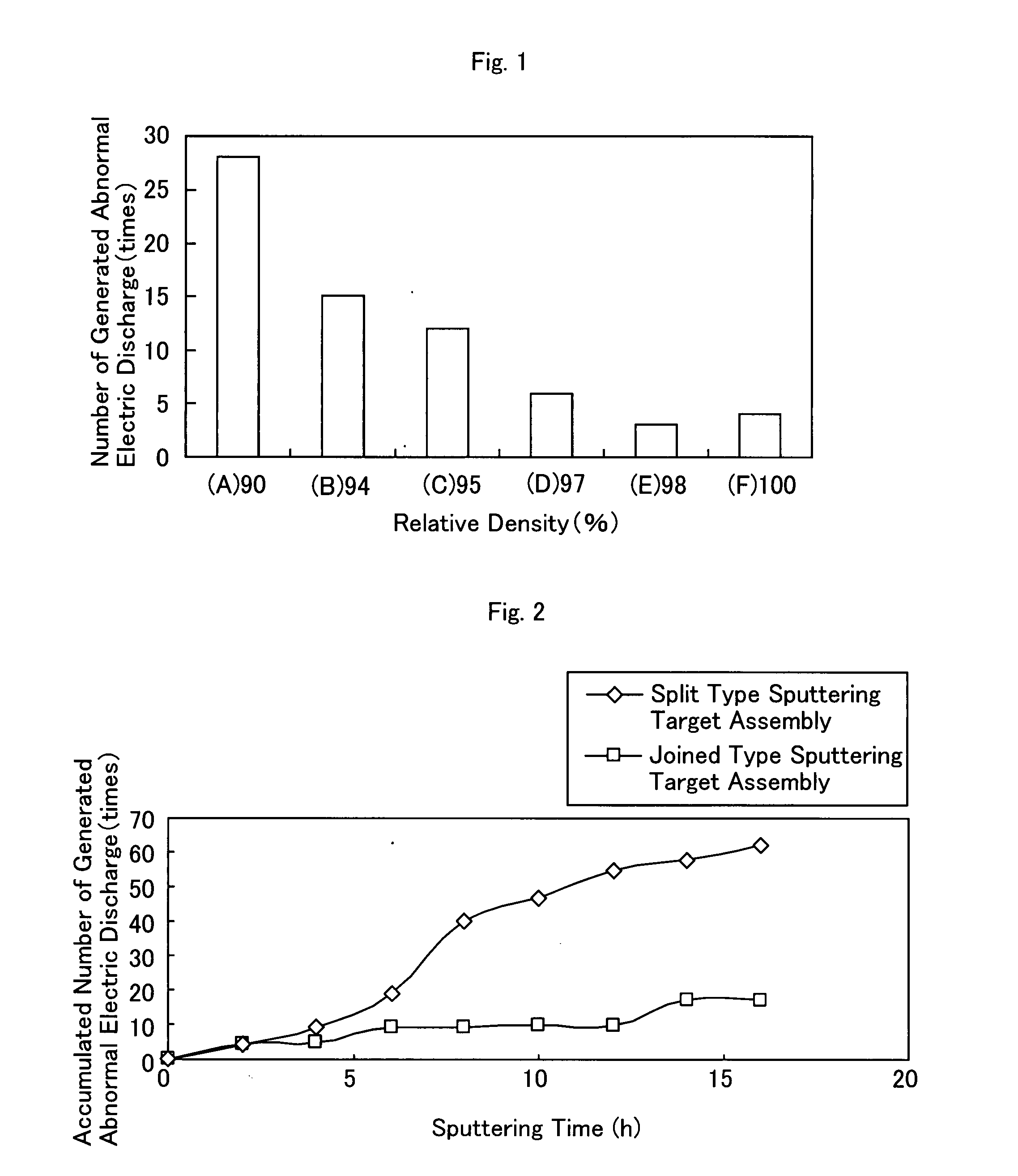
[0034]In this example, sputtering targets having different relative densities were formed while changing the condition of hot pressing. As the result, the number of abnormal electric discharges generated per unit hour was variable. Simple Mo and Ti powders were mixed together to provide a mixed powder containing Ti of 55 atomic percentages. This mixed powder was used to make sputtering targets having their relative densities of 90% (A), 94% (B), 95% (C), 97% (D), 98% (E) and 100% (F) in a hot press machine under sinter pressures of 15 MPa (A), 18 MPa (B), 20 MPa (C), 22 MPa (D), 24 MPa (E) and 25 MPa (F), respectively. These sputtering targets were used to form films for 120 minutes. The number of abnormal electric discharges generated during this film formation was counted. The results are shown in FIG. 1.

[0035]From FIG. 1, it is found that the number of generated abnormal electric discharges decreases as the relative density increases. More particularly, the number of generated ab...

example 3

[0036]In this example, sputtering targets having different oxygen concentrations were made while changing the atmosphere in which the mixed power was prepared. The resulting sputtering targets were tested with respect to their joining strength.

[0037]Simple Mo and Ti powders were mixed to provide a raw powder material containing Ti of 55 atomic percentages while changing the purity of an inert gas used in the mixing process. The resulting raw power was then used to make sputtering targets (30 mm×125 mm×12 mm) respectively having oxygen concentrations of 820 ppm, 1540 ppm, 3360 ppm and 3,780 ppm through the hot pressing process at a temperature of 1,350 degrees Celsius and a pressure of 25 MPa. These sputtering targets were diffusion joined together to provide joined type sputtering target assemblies (20 mm×200 mm×10 mm) in the HIP apparatus without any insert material under a condition in which a pressure is 100 MPa, a temperature is 1,000 degrees Celsius and a holding time is 4 hour...


PUM

PropertyMeasurementUnit
Lengthaaaaaaaaaa
Fractionaaaaaaaaaa
Fractionaaaaaaaaaa

Abstract

[Object] It is to provide a sputtering target which has an excellent adhesion to films made of Au, Cu or an alloy containing at least one of Au and Cu and also an excellent corrosion resistance and which can be used to form an Mo—Ti alloy film over a large-sized substrate.[SOLUTION] The present invention provides a sputtering target suitable for use in formation of an Mo—Ti alloy film on a substrate, characterized by that the sputtering target comprises Ti of higher than 50 atomic percentages but not exceeding 60 atomic percentages and the balance of Mo and inevitable impurities and that the relative density of the sputtering target is equal to or more than 98%. The present invention also provides a joined type sputtering target assembly formed by diffusion joining two of more of such sputtering targets, the length of the joined type sputtering target assembly being equal to or larger than 1,000 mm at least one side. The present invention further provides a method of making such a joined type sputtering target assembly.

Description

[0001]A sputtering target as well as a joined type sputtering target assembly and a method of making such a joined type sputtering target assemblyTECHNICAL FIELD[0002]The present invention relates to a sputtering target as well as a joined type sputtering target assembly and a method of making such a joined type sputtering target assembly. In particular, the present invention relates to a sputtering target suitable for use in formation of a Mo—Ti alloy film as well as a joined type sputtering target assembly comprising such sputtering targets and a method of making such a joined type sputtering target assembly.BACKGROUND ART[0003]In recent years, a thin-film transistor type liquid crystal display (TFT-LCD) has used, as an electric wiring film, a film made of any of lower resistivity metals such as Al, Cu, Ag and Au or an alloy containing at least one of said metals. Generally, such a film is inferior in any of heat resistance, corrosion resistance and adhesion which are required in ...

Claims


Application Information

Patent Timeline
IPC IPC(8): C23C14/00
CPCC23C14/3414C23C14/3407C22C14/00C23C14/542C23C14/548
Inventor NITTA, JUNICHIITO, TAKAHARUMATSUMOTO, HIROSHIITO, MANABU
Owner ULVAC INC
Learn More