Synchronous Motor

Active Publication Date: 2014-05-01
SEW-EURODRIVE GMBH & CO KG
View PDF6 Cites 6 Cited by
  • Summary
  • Abstract
  • Description
  • Claims
  • Application Information

AI Technical Summary

Benefits of technology

The invention provides a synchronous motor that is easy to manage.

Problems solved by technology

However, it is painstaking and therefore costly to produce such a one-piece, cambered, permanent-magnetic body.

Method used


Image

  • Synchronous Motor
  • Synchronous Motor

Examples


Embodiment Construction

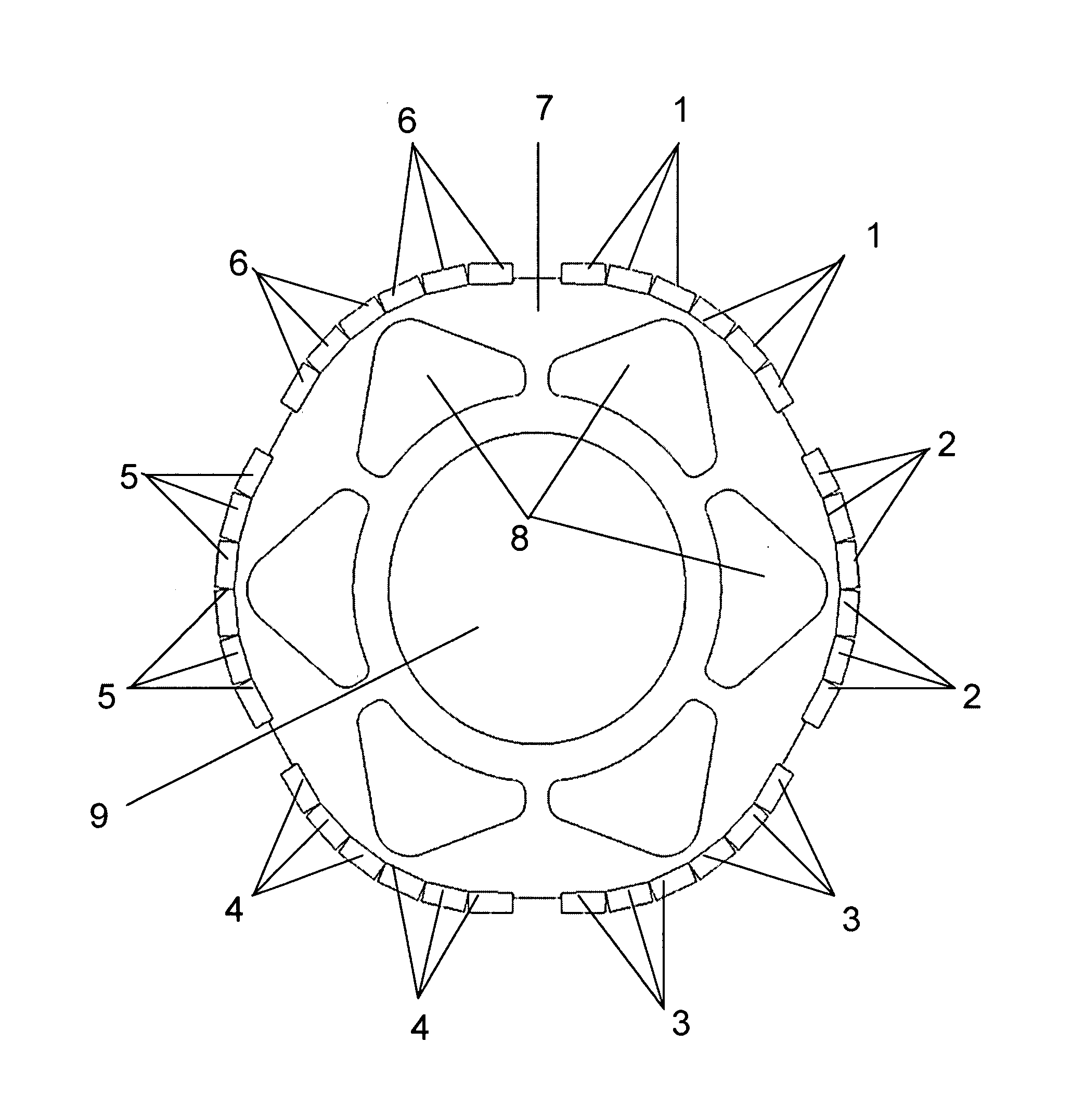
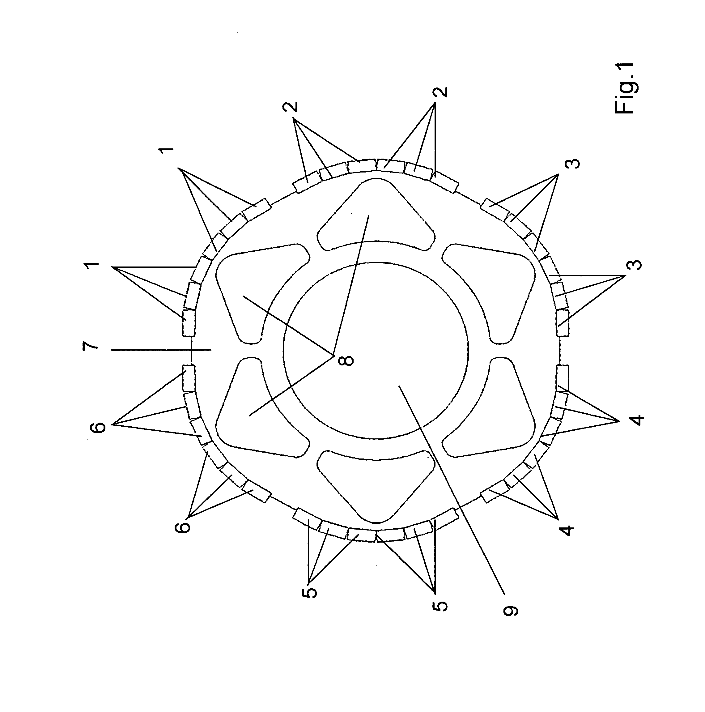
[0024]FIG. 1 shows the rotor of a synchronous motor, the rotor shaft able to be accommodated in a central opening 9 being left out.

[0025]Disposed on the rotor shaft, which is insertable in opening 9, is a laminated core 7 that is made up of joined individual laminas, preferably punch / stacked and / or welded.

[0026]Permanent magnets (1, 2, 3, 4, 5, 6) are disposed at the outer circumference of laminated core 7, one magnetic pole being formed from a plurality of permanent magnets (1, 2, 3, 4, 5, 6). In FIG. 1, each pole is formed of six permanent magnets (1, 2, 3, 4, 5, 6).

[0027]In each case gaps are located between the poles in the circumferential direction.

[0028]With the aid of the multi-piece construction of a pole, thus, the formation of each pole from six permanent magnets (1, 2, 3, 4, 5, 6), eddy-current losses are reduced.

[0029]Permanent magnets (1, 2, 3, 4, 5, 6) are magnetized in the radial direction.

[0030]Each pole has a maximum outside radius, which is centrally located in the...


PUM


Abstract

A synchronous motor includes a stator with a stator winding, and a rotor on which magnetic poles made of permanent-magnetic material are formed, each pole having a cambered outer contour, especially an outer contour cambered radially outwards, in particular, 2×p individual poles being salient in the circumferential direction, p being the number of pole pairs.

Description

FIELD OF THE INVENTION[0001]The present invention relates to a synchronous motor.BACKGROUND INFORMATION[0002]In the case of a rotor of a synchronous motor, it is well-known to use a punch / stacked laminated core, at whose outer surface permanent magnets are provided.SUMMARY[0003]Example embodiments of the present invention provide a synchronous motor which is easy to control.[0004]According to example embodiments of the present invention, a synchronous motor has a stator having a stator winding, and a rotor on which magnetic poles made of permanent-magnetic material are formed, each pole having a cambered outer contour, especially an outer contour cambered radially outwards,[0005]in particular, 2×p poles, e.g., especially individual poles, being salient in the circumferential direction, p being the number of pole pairs.[0006]This has the advantage that in the case of one pole of a pole pair, the permanent magnets are disposed so as to be magnetized radially outwards, and in the case ...

Claims


Application Information

Patent Timeline
IPC IPC(8): H02K21/14
CPCH02K21/14H02K29/03H02K2201/03H02K1/2781H02K1/2706H02K2213/03
Inventor NESTLER, HELMUT
Owner SEW-EURODRIVE GMBH & CO KG
Why Eureka
Try Eureka