Method of manufacturing a rotary shaft

Inactive Publication Date: 2005-03-31
HOSHIZAKI ELECTRIC CO LTD
View PDF5 Cites 6 Cited by
  • Summary
  • Abstract
  • Description
  • Claims
  • Application Information

AI Technical Summary

Benefits of technology

[0007] The present invention has been made in order to solve the problems described above. An object of the present invention is to provide a method of manufacturing a rotary shaft in which the strength of joining portions where members are friction welded can be increased.

Problems solved by technology

Further, an excessive amount of machining time is required.
There is a problem, however, in that friction-welded joining portions have a lower strength compared to the parent material of the rotary shaft.
Further, a problem arises in terms of the strength of the joining portions where different diameter round bars are joined, that is, when the diameters of members to be joined differ as with an auger, because the joining portions overlap with corner portions (fillet portions) where stress concentrations develop.

Method used


Image

  • Method of manufacturing a rotary shaft
  • Method of manufacturing a rotary shaft
  • Method of manufacturing a rotary shaft

Examples


embodiment 1

[0016] An auger of an auger type ice making machine, which is shown as an example of a rotary shaft according to the present invention, is explained in Embodiment 1.

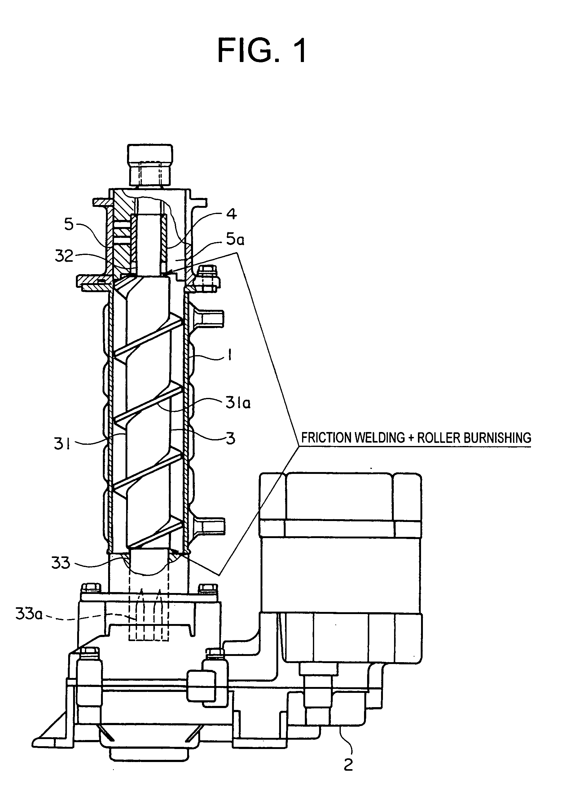
[0017]FIG. 1 shows the structure of an ice making mechanism portion of the auger type ice making machine.

[0018] An auger 3 that has a helical blade 31a arranged in a helical manner on an outer circumference thereof is disposed in an inner portion of a cylindrical cooling cylinder 1. The auger 3 is rotatably supported at upper and lower end portions thereof.

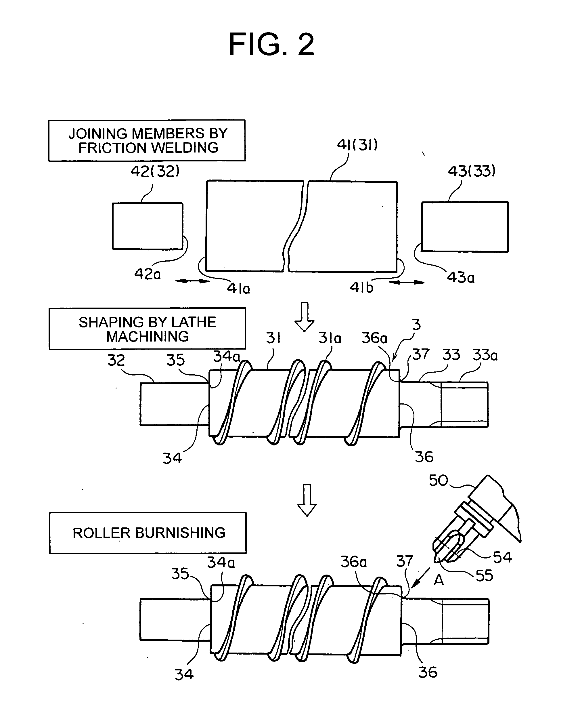
[0019] The auger 3 is composed of a main body portion 31 provided with the helical blade 31a, and an upper shaft portion 32 and a lower shaft portion 33 that each have an outer diameter that is smaller than that of the main body portion 31. The upper shaft portion 32 is supported by a bearing 4 so as to be freely rotatable. Further, the lower shaft portion 33 is also freely rotatably supported, and in addition, there is a spline 33a formed in an end portion of the l...

embodiment 2

[0041] In Embodiment 1, roller burnishing is performed one time after joining the members by friction welding and performing shaping by lathe machining. In this embodiment, however, as shown in FIG. 5, roller burnishing is performed two times on the same location, with a predetermined interval of time therebetween.

[0042] It is preferable that the time interval be from 1 to 2 months.

[0043] Roller burnishing can increase fatigue strength if performed a plurality of times on the same location. However, when performed too many times, the effect of roller burnishing lessens. Further, if roller burnishing is performed a plurality of times in succession without allowing for a time interval, the fatigue strength increasing effect lessens. It has been found that the fatigue strength can be increased by performing roller burnishing two times on the same location, with a long period of time interval of 1 to 2 months therebetween.

[0044] It should be noted that, although roller burnishing is ...


PUM

PropertyMeasurementUnit
Timeaaaaaaaaaa

Abstract

Three solid round bars are prepared as auger members, respectively as a main body member, an upper shaft member, and a lower shaft member. End surfaces of the members are coaxially joined together by friction welding. Turning machining is then performed by using a lathe, forming a helical blade, a spline, and the like. In addition, burnishing is performed on a corner portion that includes an outer circumferential edge of a joining surface where friction welding is performed, and another corner portion that includes an outer circumferential edge of another joining surface where friction welding is performed. The burnishing is performed by pressing a roller, which is freely rotatable about a roller support shaft center of a Superoll, toward the corner portions of the rotating auger. Roller burnishing may also be performed two times on the same location, with a predetermined time interval therebetween.

Description

BACKGROUND OF THE INVENTION [0001] 1. Field of the Invention [0002] The present invention relates to a method of manufacturing a rotary shaft that includes a rotary shaft main body, and a shaft portion that is bonded coaxially to the rotary shaft main body. In particular, the present invention relates to a method of manufacturing an auger of an auger type ice making machine. [0003] 2. Description of the Related Art [0004] A rotary shaft manufactured from metal and used in transferring torque, such as an auger in an auger ice making machine, is generally not limited to a hollow round bar or a hollow solid bar having a uniform diameter. In the case of an auger, for example, the size of the diameter differs between auger shaft portions at both ends and an auger main body portion having a helical blade. If the rotary shaft is to be formed by turning from one round bar having a uniform diameter as for such an auger, a large amount of turning becomes necessary to machine a shaft portion h...

Claims


Application Information

Patent Timeline
IPC IPC(8): B23K20/12F25C1/14
CPCB23K20/129B23K20/12
Inventor MIZUTANI, YASUKISUGIE, HIROYUKI
Owner HOSHIZAKI ELECTRIC CO LTD
Why Eureka
Try Eureka