Image editing device and print/embroidery data creating device

a technology of image editing and printing, which is applied in the direction of embroidering machines, automatic machines, textiles and paper, etc., can solve the problems of troublesome and heavy burden on users, the resultant images of printing and embroidering do not have consistency between their positions and sizes, and the position and/or size of the output image remains in error

Active Publication Date: 2005-08-18
BROTHER KOGYO KK
View PDF6 Cites 52 Cited by
  • Summary
  • Abstract
  • Description
  • Claims
  • Application Information

AI Technical Summary

Benefits of technology

[0044] Further, the image editing device may include a reading system that reads a surface of the fabric as captured image data, and a display controlling system that displays the captured image data read with the reading system on the display device together with the input image in an overlapped manner. The area designating system may allow the user to refer to the captured image data when the specific area is designated.

Problems solved by technology

When the print data and the embroidery data are created independently, the resultant images of printing and embroidering do not have consistency therebetween in their positions and sizes.
Such an adjustment should be done manually, and accordingly, it is troublesome and heavy burden to the user.
However, since the embroidery data and print data may not have consistency in position and size, even if a mechanical adjustment is accurate, there still remains some errors in position and / or size of the output images (i.e., printed / embroidered patterns).
HEI 5-272046 is used, the user is still required to adjust the position and / or size of the images, which is a troublesome and time-consuming job for the operator.
In such a case, a further problem may arise.
The above-described publications cannot deal with a printing operation with respect to a fabric including a plurality of areas having different permeability.

Method used


Image

  • Image editing device and print/embroidery data creating device
  • Image editing device and print/embroidery data creating device
  • Image editing device and print/embroidery data creating device

Examples


first embodiment

[0116]FIG. 4 is a flowchart illustrating an overall operation from input of image data to output of image pattern on an object (e.g., T-shirt). FIG. 5 shows an example of the input image data.

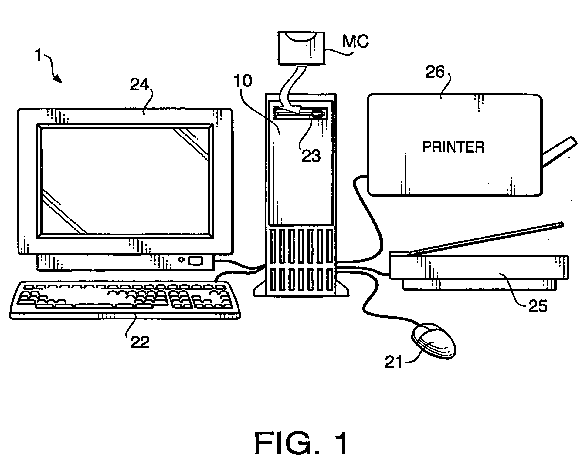
[0117] As shown in FIG. 4, a user of the print / embroidery data creating device 1 inputs image data in the main body 10. The image data to be input may be created using the image scanner 25, or retrieved from an external storage such as the hard disk, CD-ROM, CD-R and input to the main body 10. According to the first embodiment, it is assumed that a photograph of a person as shown in FIG. 5 is scanned by the image scanner 25 to generate the image data.

[0118] Next, upon instruction of the user, a print / embroidery data creating procedure is executed (S202). By the print / embroidery data creating procedure, the print / embroidery data is created based on the image data input in S201.

[0119] The print / embroidery data creating procedure will be described in detail.

[0120]FIG. 6 is a flowchart illustra...

second embodiment

[0193] Next, a print / embroidery data creating device according to a second embodiment will be described. According to the first embodiment, only the area set as the usable color area is embroidered. That is, in the first embodiment, for the area other than the usable color area, the second embroidery data is created. Then, in the first embodiment, the embroidery with the white thread is formed based on the second embroidery data. In the second embodiment, for the print area, only the printed image by the inkjet printer is formed.

[0194]FIGS. 18A-18C illustrate an image pattern output by a print / embroidery data editing procedure according to the second embodiment. That is, FIGS. 18A-18C show an embroidered pattern represented by embroidery data, a printed pattern represented by print data, and a resultant pattern formed on a T-shirt, respectively.

[0195]FIG. 18A shows the pattern represented by the embroidery data, which indicates that only the hair portion of the face is embroidered...

third embodiment

[0197] Next, a print / embroidery data creating device according to a third embodiment will be described. The hardware configuration of the print / embroidery data creating device according to the third embodiment is similar to that of the first embodiment. According to the third embodiment, it is assumed that image data representing an image 4 shown in FIG. 21 is scanned with the image scanner 25 in S201 (see FIG. 4). As shown in FIG. 21, the image 4 is configured such that a left-hand side half includes a pixel area 4a which is black, and a right-hand side half includes a pixel area 4b which is white. At the boundary of the black pixel area 4a and the white pixel area 4b, a pixel area 4c is formed, in which the color gradually changes from black to white in the left-to-right direction.

[0198] In S202, the print / embroidery data is created based in the input data 4. FIG. 22 is a flowchart illustrating the main flow of the print / embroidery data creating procedure. The print / embroidery da...


PUM


Abstract

A print/embroidery data creating device is provided with a usable color designating system, an output information setting system, a pixel examining system, an area setting system that sets a pixel area determined to correspond to the usable color as a usable color area and sets an area which does not correspond to the usable color area as a print area, an embroidery data creating system. The usable color area is output with the size set by the output information setting system at the position set by the output information setting system by the embroidering machine, and a print data creating system that creates print data such that a pixel area set as the print area by the area setting system is output as printed area with a color corresponding to the pixel color, the print area being output with the size set by the output information setting system at the position set by the output information setting system by the printer.

Description

INCORPORATION BY REFERENCE [0001] This application claims priority from Japanese Patent Applications No. 2004-040938, filed on Feb. 18, 2004, and No. 2004-043172, filed on Feb. 19, 2004, No. 2004-096584, filed on Mar. 29, 2004, the entire subject matters of the applications are incorporated herein by reference thereto. BACKGROUND OF THE INVENTION [0002] The present invention relates to an image editing device capable of creating print data, and a print / embroidery data creating method, device and a printing / embroidering system that create print / embroidery data. [0003] Conventionally, there has been known a printing system that prints, in accordance with image data representing people, animals, sceneries and the like, an image pattern on a fabric such as a T-shirt with, for example, an inkjet printer. On the other hand, there has also been know an embroidering system that embroiders, in accordance with the image data, an image pattern on a fabric such as the T-shirt with, for example,...

Claims


Application Information

Patent Timeline
Patent Type & Authority Applications(United States)
IPC IPC(8): D05B19/08D05B21/00D05C5/02
CPCD05B19/08
Inventor NIIMI, AKIKOYAMADA, KENJI
Owner BROTHER KOGYO KK
Why Eureka
Try Eureka