Mine sifting attachment having transverse blades

Inactive Publication Date: 2005-09-01
UNITED STATES OF AMERICA THE AS REPRESENTED BY THE SEC OF THE ARMY
10 Cites 7 Cited by

AI-Extracted Technical Summary

Problems solved by technology

A drawback to this equipment is that the sifting basket is often clo...

Benefits of technology

[0005] This and other objects of the invention are achieved in one aspect by an improved minesweeper having a two-sided frame adapted to be coupled to and pushed by a tractor and a rake pivoted from each side of the frame by respective pairs of coupling bars of different lengths so that as the rake moves away from the frame to bury itself in the soil, the coupling bars rotate it to a less aggressive digging angle that prevents the rake from stalling the tractor, wherein the improvement comprises means connected to the frame for catching and sifting mines, soil, rocks and other objects buried in the soil passing over the rake without small amounts of vegetation and variances in soil conditions clogging the catc...

Abstract

An improved minesweeper having a two-sided frame adapted to be coupled to and pushed by a tractor and a rake pivoted from each side of the frame by respective pairs of coupling bars of different lengths so that as the rake moves away from the frame to bury itself in the soil, the coupling bars rotate it to a less aggressive digging angle that prevents the rake from stalling the tractor, wherein the improvement comprises apparatus connected to the frame for catching and sifting mines, soil, rocks and other objects buried in the soil passing over the rake without small amounts of vegetation and variances in soil conditions clogging the catching and sifting means.

Application Domain

Defence devicesLifters +3

Technology Topic

EngineeringTractor +2

Image

  • Mine sifting attachment having transverse blades
  • Mine sifting attachment having transverse blades

Examples

  • Experimental program(1)

Example

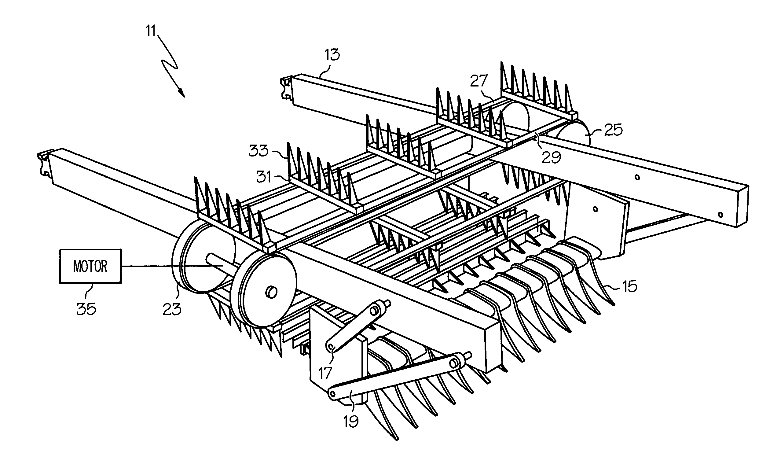
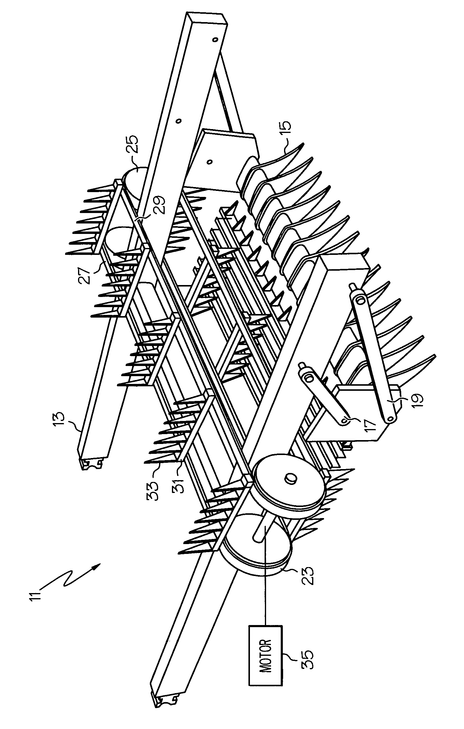
[0009] The FIGURE shows the minesweeper 11 incorporating the invention. The minesweeper has a two-sided frame 13 adapted to be coupled to and pushed by a tractor (not shown). A rake 15 is pivoted from each side of the frame by respective pairs of coupling bars 17 and 19 of different lengths so that as the rake moves away from the frame to bury itself in the soil, the coupling bars rotate it to a less aggressive digging angle that prevents the rake from stalling the tractor. The minesweeper as thus far described follows the teachings of my U.S. Pat. No. 6,330,920 B1, the disclosure of which is hereby incorporated by reference.
[0010] In accordance with the present invention, there is provided improvement by substituting for the sifting basket of the prior art minesweeper a novel means for catching and sifting mines, soil, rocks and other objects buried in the soil passing over the rake 15, so that small amounts of vegetation and variances in soil conditions do not clog the catching and sifting means.
[0011] While the catching and sifting means may take a variety of forms, conveniently it may take the form shown in the FIGURE of a plurality of spaced fixed vanes 21 running across the bottom of the frame 13 from one side of the frame to the other side, two pairs of rollers, one pair of rollers 23 mounted on the one side of the frame and the other pair of rollers 25 mounted on the other side of the frame, and a pair of endless chains 27 and 29 running across the top of the frame and around the rollers. In addition, the catching and sifting means includes a plurality of spaced beams 31 carried by the pair of chains, the beams lying across the spaced fixed vanes, a plurality of teeth 33 mounted on the beams, and a means 35, such as a hydraulic motor, for example a Kawasaki® company model STAFFA HMB080 hydraulic motor, for turning the rollers.
[0012] In operation, the frame 13 is coupled to and pushed by a tractor over a minefield. The rake 15 moves away from the frame to bury itself in the soil and the coupling bars rotate it to a less aggressive digging angle. The rake 15 digs into the topsoil layer and mines, soil, rocks and other objects buried in the soil pass over the rake and are caught by the vanes 21. The hydraulic motor 35 turns the rollers 25 to move the chains 27 and 29 around a loop at two to four miles per hour (2-4 mph) so that the teeth 33 mounted on the beams 31 rake the soil and the objects sideways along the vanes 21, the teeth partially meshing with the vanes and forcing the soil to fall through while mines, and other objects larger than the vane spacing are carried along the tops of the vanes and are ejected to the side of the frame 13.
[0013] It is obvious that many modifications and variations of the present invention are possible in light of the above teachings. It is therefore to be understood that within the scope of the appended claims, the invention may be practiced otherwise than as described.

PUM

no PUM

Description & Claims & Application Information

We can also present the details of the Description, Claims and Application information to help users get a comprehensive understanding of the technical details of the patent, such as background art, summary of invention, brief description of drawings, description of embodiments, and other original content. On the other hand, users can also determine the specific scope of protection of the technology through the list of claims; as well as understand the changes in the life cycle of the technology with the presentation of the patent timeline. Login to view more.
Why Eureka
Try Eureka