
Threadless conduit fitting including continuous compression ring

Active Publication Date: 2005-09-01
THOMAS & BETTS INT INC
View PDF6 Cites 12 Cited by
  • Summary
  • Abstract
  • Description
  • Claims
  • Application Information

AI Technical Summary

Benefits of technology

[0008] A connector fitting that provides a tactile indication of proper torquing of the gland nut is also provided by the invention. The fitting includes a connector body, a gland nut threadably coupled to the connector body, a continuous metal compression ring, and means for providing a tactile indication that the gland nut has been properly torqued. Such means may preferably include a stop, preferably in the form of an annular ridge, formed on the compression ring that s

Problems solved by technology

Such rings can leave a gap at the area of the split.
In addition to increasing material and labor cost, the use of

Method used


Image

  • Threadless conduit fitting including continuous compression ring
  • Threadless conduit fitting including continuous compression ring
  • Threadless conduit fitting including continuous compression ring

Examples


Example

DETAILED DESCRIPTION OF THE DRAWINGS

[0014] A connector fitting for a rigid conduit and a method for mounting such a fitting are provided. While preferred embodiments of the invention are disclosed herein, it is to be understood that the invention is not limited to the preferred embodiments and is to be interpreted by the appended claims.

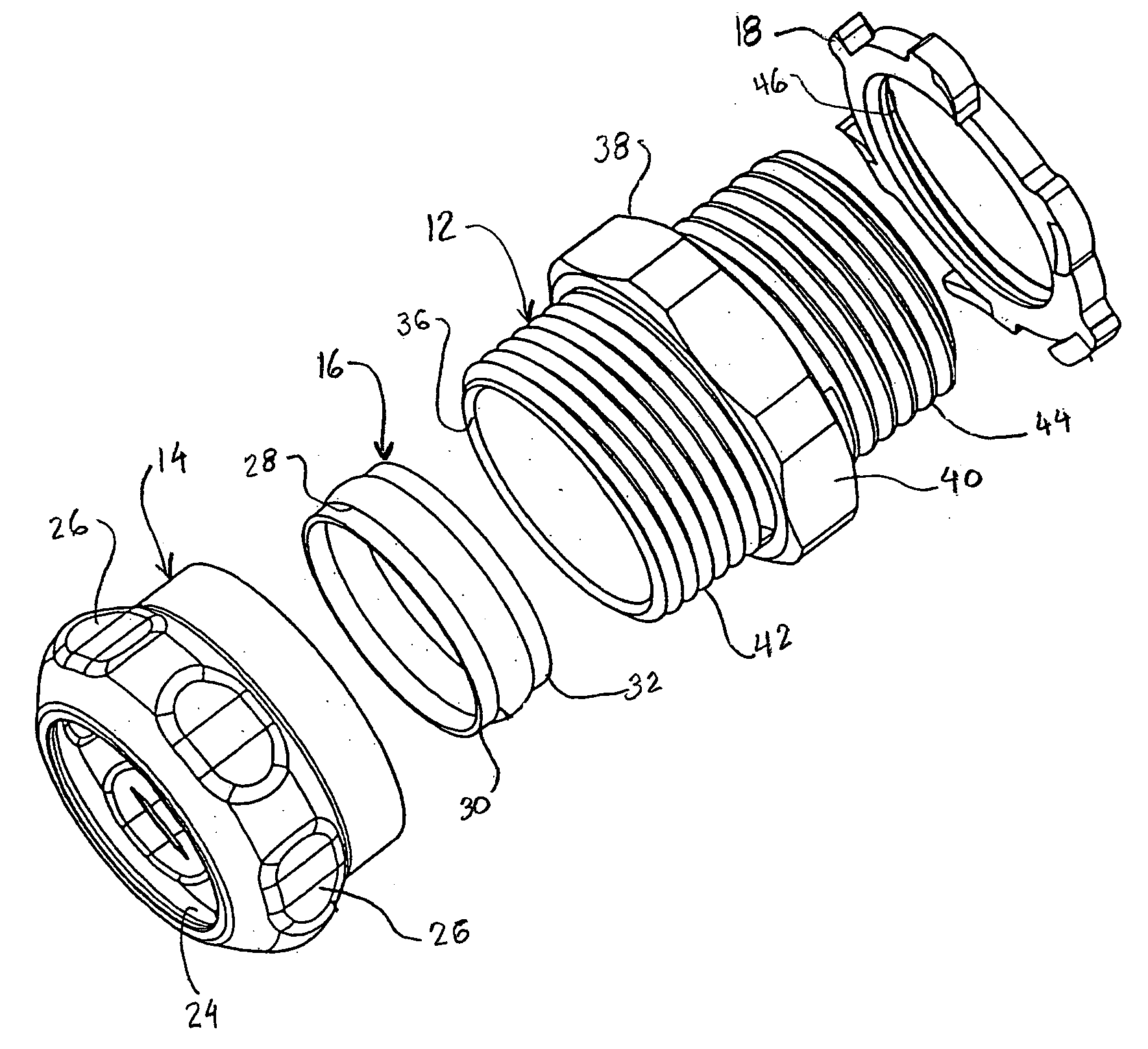
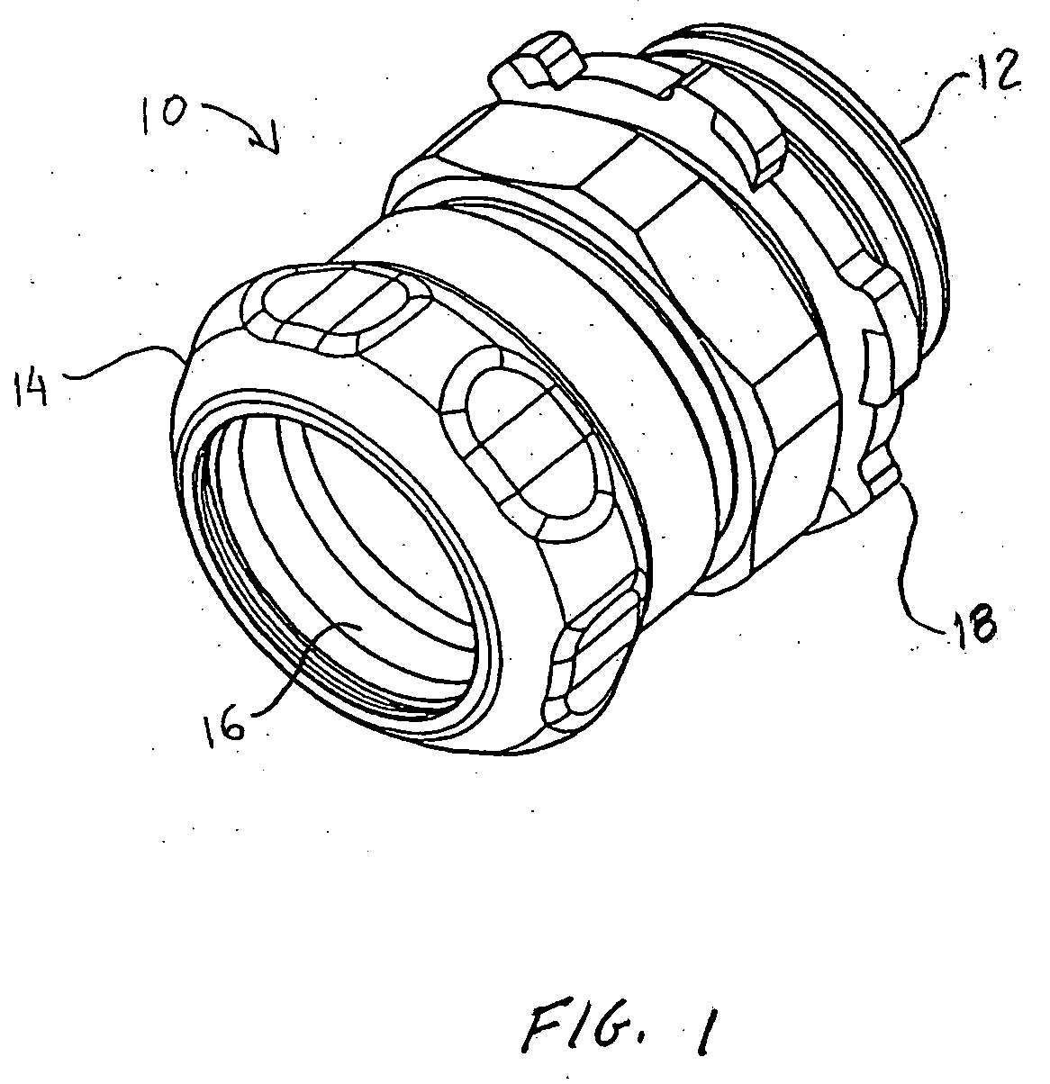
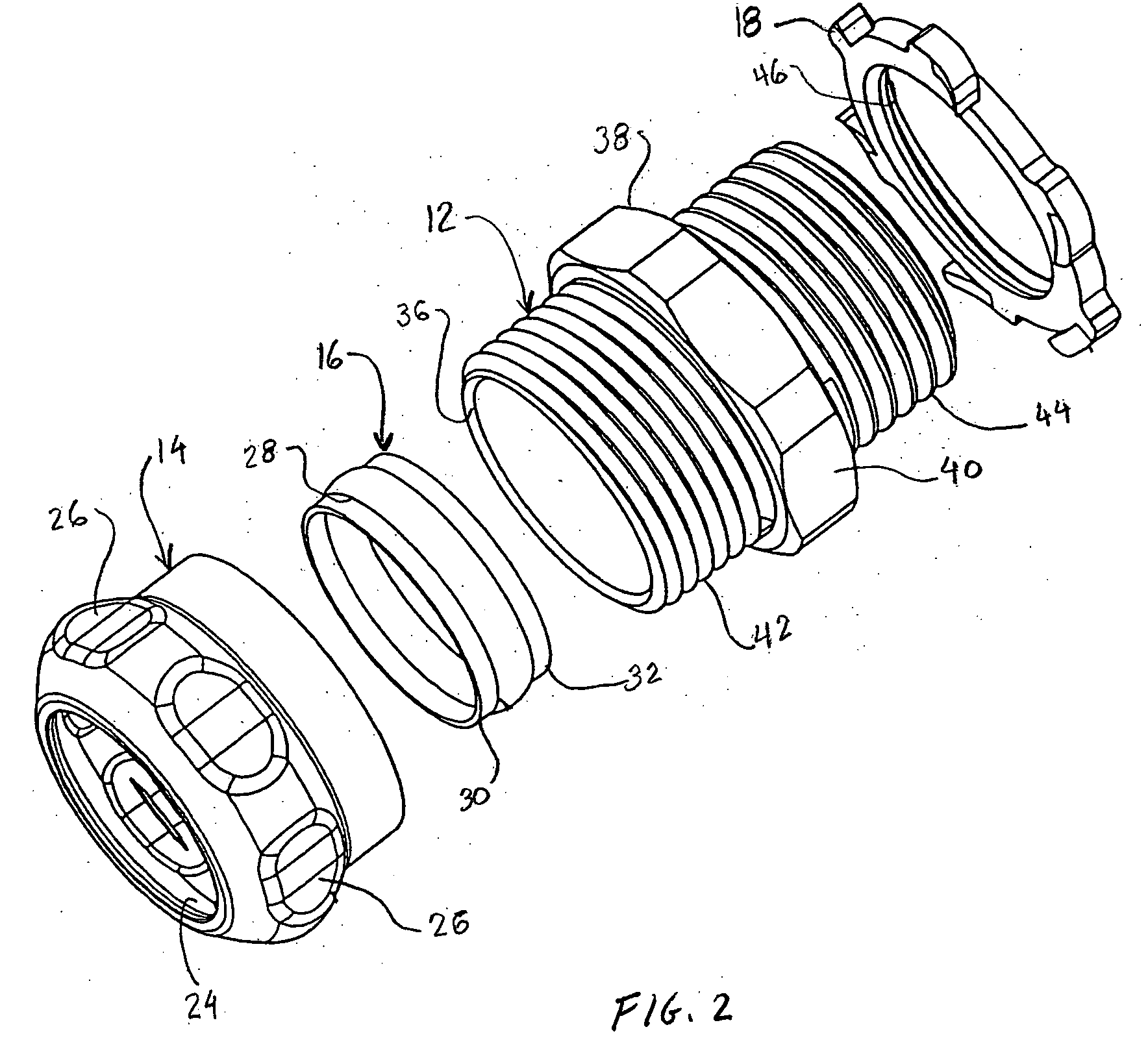
[0015] Referring to FIG. 1, a connector fitting 10 intended for coupling to a rigid conduit is shown as assembled. The connector fitting includes a connector body 12, a gland nut 14 threadably coupled to the connector body 12, and a compression ring 16. A locknut 18 is threadably coupled to the connector body on the end portion thereof opposite to the gland nut 14. These elements are shown individually in FIG. 2 and in cross section in FIG. 3. All of these elements are preferably made from moisture-resistant materials, particularly where the fitting is intended for outdoor use. If made from metal and used in conjunction with rigid metal conduit suc...


PUM


Abstract

A connector fitting for a threadless conduit and a method of securing such a fitting are provided. The connector fitting includes a connector body, a gland nut, and a continuous metal compression ring. The compression ring includes an annular stop and a pair of end portions. Upon tightening the gland nut, one end portion of the compression ring is urged between the connector body and conduit while the other end of the compression ring is press fit between the gland nut and conduit to form a rain tight seal. One or more indicators are provided for indicating that the gland nut has been properly torqued.

Description

BACKGROUND OF THE INVENTION [0001] 1. Field of the Invention [0002] The field of the invention relates to threadless conduit fittings and methods for securing such fittings to a conduit such as electrical metallic tubing, intermediate metallic conduit, or other rigid metal electrical conduit. [0003] 2. Brief Description of the Related Art [0004] Connector fittings for electrical conduits may be of the type that employ a compression ring used to engage the outer surface of such a conduit. A threaded connector body is coupled to a gland nut, and the compression ring is positioned within the gland nut. When the gland nut is tightened, the compression ring is subjected to forces that cause it to bear tightly against the conduit. Fittings for rigid metal conduits of various diameters and wall thicknesses have been known to include split metal compression rings. Such rings can leave a gap at the area of the split. Various solutions have been proposed to address this problem, such as a res...

Claims


Application Information

Patent Timeline
IPC IPC(8): F16L19/06F16L19/075H02G3/06H02G3/18
CPCF16L19/061H02G3/06F16L19/075
Inventor PYRON, ROGER
Owner THOMAS & BETTS INT INC
Learn More