Hydraulic tensioner

a technology of hydraulic tensioner and tensioner body, which is applied in the direction of wound springs, belts/chains/gearings, wound springs, etc., can solve the problem of not significantly increasing the production cost of the tensioner, and achieve the effect of reliable incorporation into the tensioner

Active Publication Date: 2005-09-08
TSUBAKIMOTO CHAIN CO
View PDF18 Cites 9 Cited by
  • Summary
  • Abstract
  • Description
  • Claims
  • Application Information

AI Technical Summary

Benefits of technology

[0009] The close-wound portion fits over the retainer and can be reliably incorporated into the tensioner by sliding onto the retainer of the check valve unit without expansion or contraction. Wear and breakage, which are liable to occur in the retainer of a conventional check valve unit are prevented, and the plunger-biasing spring can bias the plunger reliably without being restrained by the retainer.

Problems solved by technology

Furthermore, even if the tensioner properties are varied significantly, the production cost of the tensioner is not significantly increased.

Method used


Image

  • Hydraulic tensioner
  • Hydraulic tensioner
  • Hydraulic tensioner

Examples


Embodiment Construction

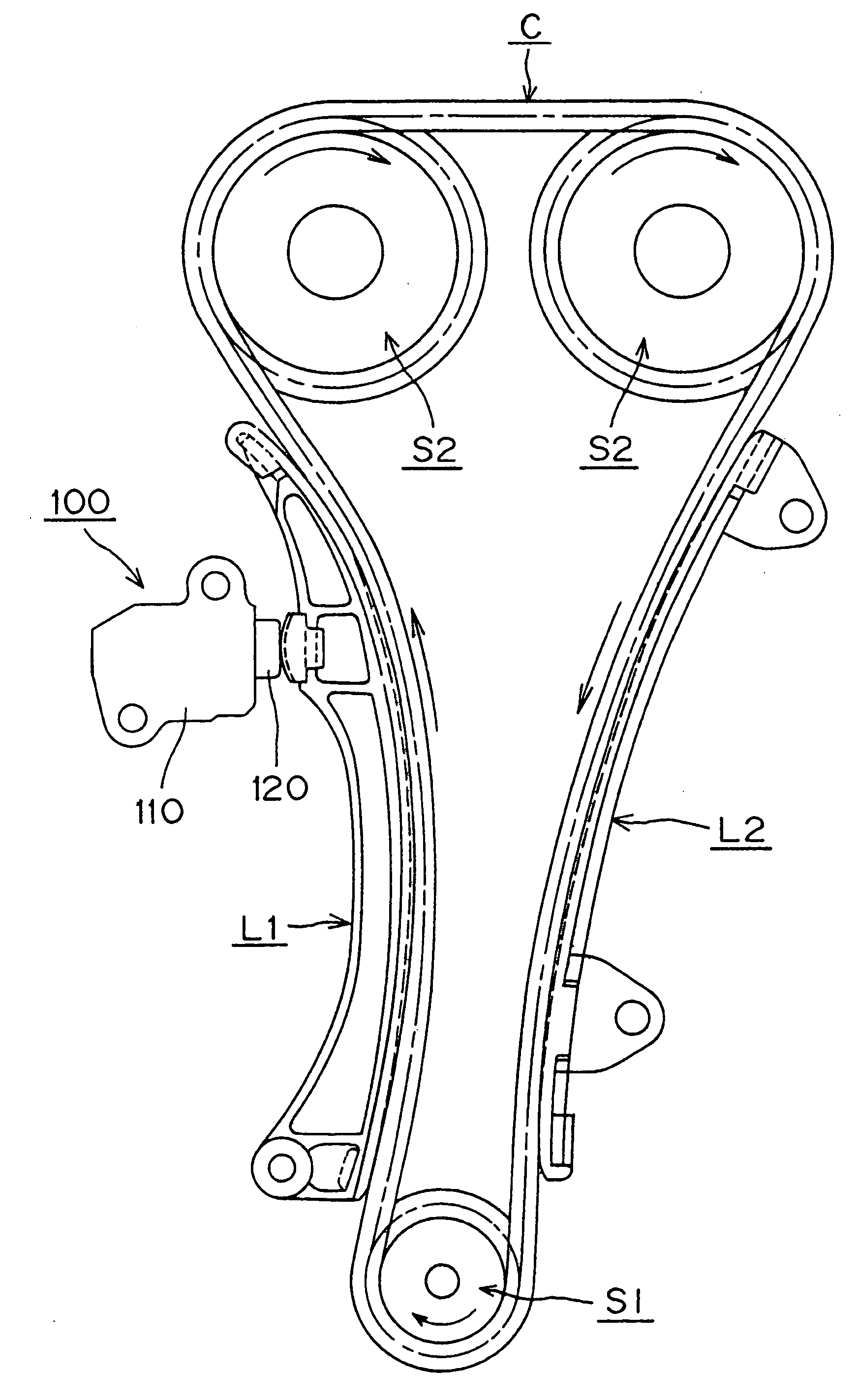
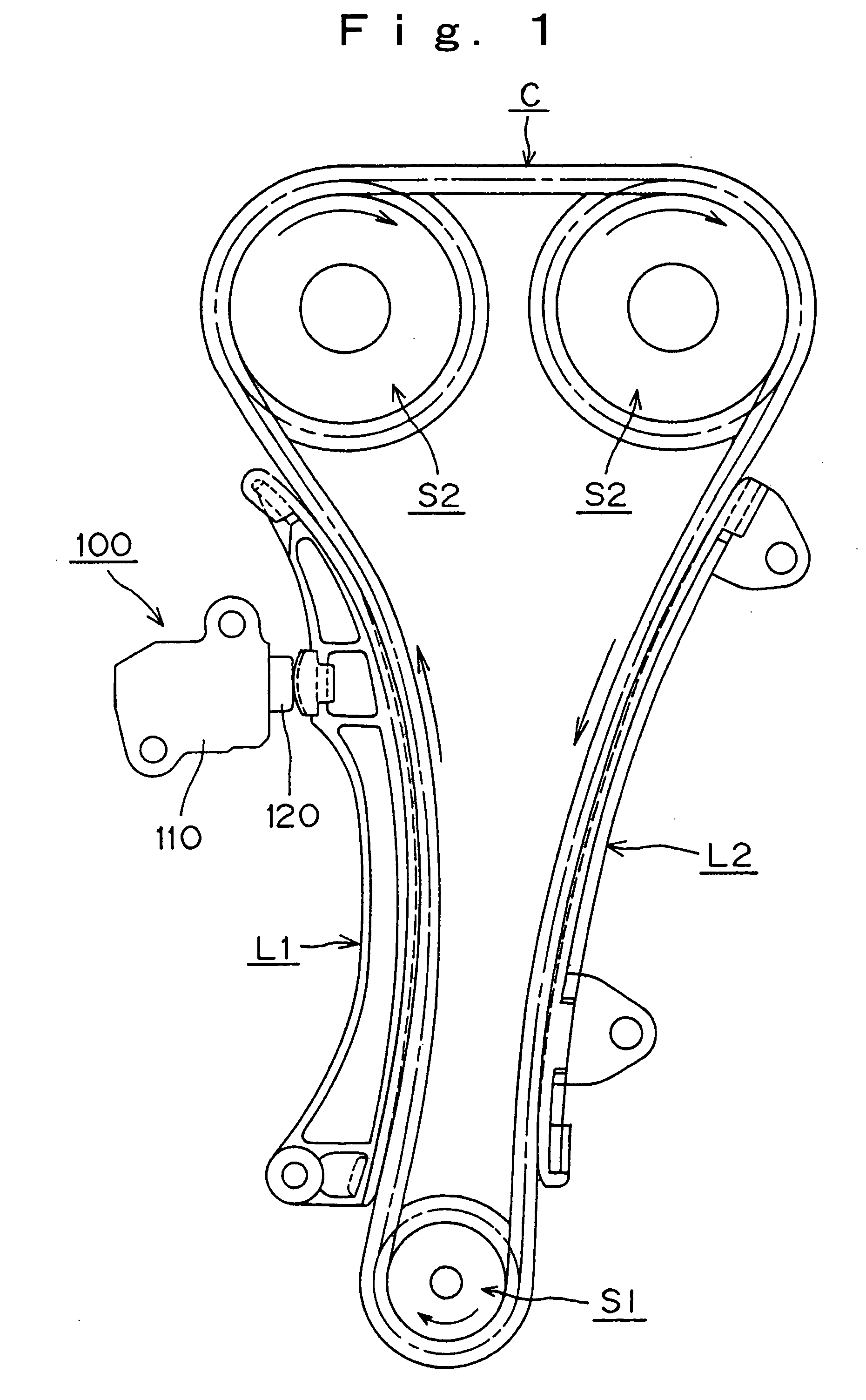
[0017] As shown in FIG. 1, a tensioner 100 may be attached to an engine body (not shown) adjacent the slack side of a timing chain C, which is in meshing engagement with a driving sprocket S1, rotated by the crankshaft of the engine, and two driven sprockets S2, which are fixed on engine valve-operating camshafts. Arrows show the directions of movement of the timing chain and sprockets. A plunger 120, which protrudes from the tensioner housing 110, presses a pivoted lever L1 against the back surface of the timing chain C on the slack side, i.e., the side moving from the drive sprocket S1 to one of the driven sprockets S2. A fixed guide L2, guides the tension side of the timing chain C.

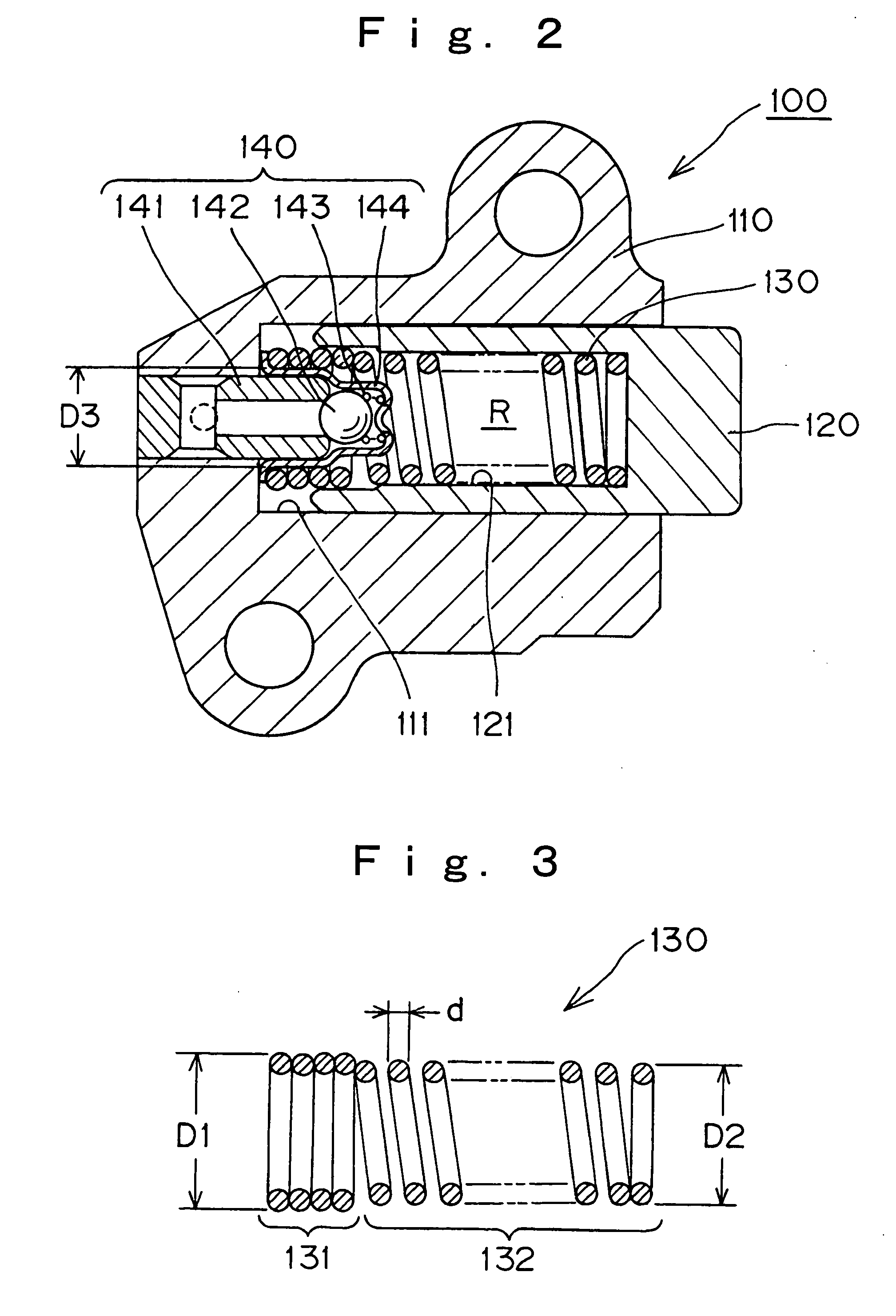
[0018] In the hydraulic tensioner 100, shown in FIG. 2, the plunger 120, the outside of which is cylindrical, is slidable in a plunger-accommodating hole 111 formed in the housing 110. A hollow portion 121, formed inside the plunger and having an open end, accommodates a coiled, plunger-biasing compre...


PUM


Abstract

A hydraulic tensioner comprises a hollow plunger slidable in a plunger-accommodating hole in a housing, the plunger and housing forming a high pressure oil chamber. A check valve unit, which includes a check ball and a check ball retainer, allows oil to flow into the oil chamber, but prevents reverse flow. A plunger-biasing spring, disposed inside the high-pressure chamber includes a close-wound portion fitting over the retainer of the check valve unit, and a portion having spaced windings, which extends and compresses axially with protruding and retracting movement of the plunger. The outer diameter of the close-wound portion is greater than the outer diameter of the portion having spaced windings.

Description

FIELD OF THE INVENTION [0001] This invention relates to hydraulic tensioners used for maintaining proper tension in flexible power transmission media such as timing chains or timing belts in vehicle engines. BACKGROUND OF THE INVENTION [0002] Hydraulic tensioners have been widely used to maintain proper tension in, and prevent vibration of, power transmission media such as timing chains, which transmit rotation from a crankshaft to one or more camshafts in a vehicle engine. A typical hydraulic tensioner is shown and described in Japanese Laid-open Patent Publication No. Hei-11-33685 (page 1, FIG. 5). [0003] As shown in FIG. 5 of the present application, in a conventional hydraulic tensioner 500, a plunger 520 is slidable in a plunger-accommodating hole 511, formed in a housing 510. A blind bore 521 is formed in the interior of the plunger 520, and a plunger-biasing spring 530, which biases the plunger 520 in the protruding direction, is disposed between the bottom of the plunger-acc...

Claims


Application Information

Patent Timeline
Patent Type & Authority Applications(United States)
IPC IPC(8): F16F1/06F16H7/06F16H7/08
CPCF16H7/0848F16H2007/0806F16H2007/0859F16H2007/0853F16H2007/0812
Inventor NAMIE, TSUTOMU
Owner TSUBAKIMOTO CHAIN CO
Why Eureka
Try Eureka