Unlock instant, AI-driven research and patent intelligence for your innovation.

Disk drive/player positioning structure

Inactive Publication Date: 2005-09-08
TATUNG COMPANY
View PDF5 Cites 5 Cited by
  • Summary
  • Abstract
  • Description
  • Claims
  • Application Information

AI Technical Summary

Benefits of technology

[0008] The present invention has been accomplished under the circumstances in view. It is therefore the main object of the present invention to provide a disk drive / player positioning structure, which saves much labor and manufacturing time, thereby reducing the manufacturing cost.
[0010] Because it is easy to lock / unlock the disk drive / player simply by means of moving the disk drive / player forwards or backwards without the use of screws, the installation of the disk drive / player requires less number of parts and saves much cost and labor.

Problems solved by technology

Because it is easy to lock / unlock the disk drive / player simply by means of moving the disk drive / player forwards or backwards without the use of screws, the installation of the disk drive / player requires less number of parts and saves much cost and labor.

Method used


Image

  • Disk drive/player positioning structure
  • Disk drive/player positioning structure
  • Disk drive/player positioning structure

Examples


Embodiment Construction

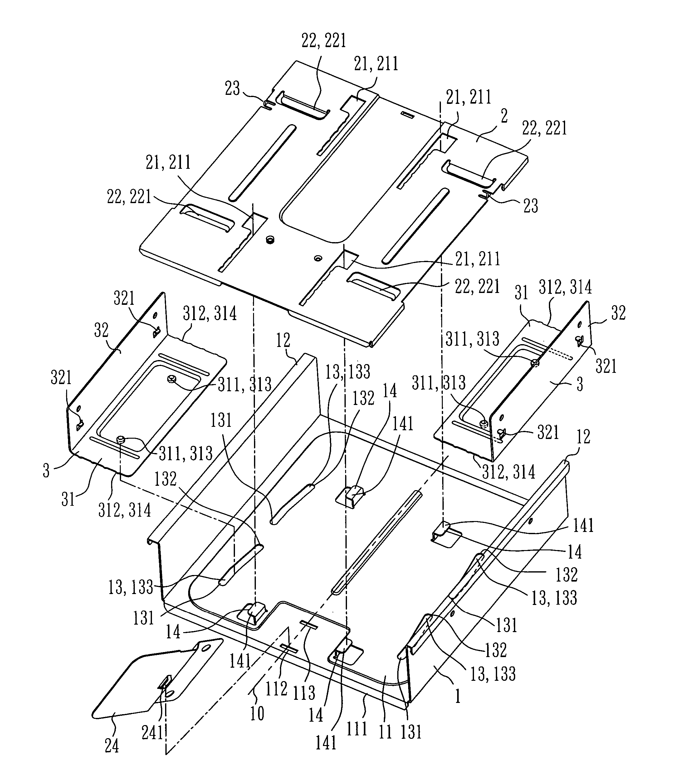
[0020] Referring to FIGS. 2 and 3, a disk drive / player positioning structure in accordance with the present invention is shown comprised of a bracket 1, a sliding bottom plate 2, two sliding side plates 3, and a disk drive / player 4.

[0021] The bracket 1 comprises a bottom wall 11 and two upright sidewalls 12 at two sides of the bottom wall 11. The bottom wall 11 defines a longitudinally extended centerline 10, having two longitudinal guides 13 equally spaced from the centerline 10 at two sides, two longitudinal sliding tracks 14 equally spaced from the centerline 10 at two sides between the centerline 10 and the longitudinal guides 13, and a first locating hole 112 and a second locating hole 113 longitudinally aligned on the middle adjacent to the front edge 111 of the bottom wall 11. According to this embodiment, each longitudinal guide 13 comprises two obliquely longitudinally extended sliding slots 133. Each obliquely longitudinally extended sliding slot 133 has a front end porti...


PUM


Abstract

A disk drive / player positioning structure includes a bracket, a sliding bottom plate coupled and movable forwards / backwards relative to the bracket, two sliding side plates coupled between the sliding bottom plate and the bracket for longitudinal displacement with the sliding bottom plate and transversely movable to each other relative to the bracket, and a disk drive / player mounted on the sliding bottom plate. The disk drive / player is locked that the disk drive / player is pushed backwards with the sliding bottom plate relative to the bracket and the sliding side plates are moved inwards toward each other to force locating rods thereof into respective locating holes in the disk drive / player, and is unlocked that the disk drive / player is pushed forwards with the sliding bottom plate relative to the bracket and the sliding side plates are moved outwards to disengage the locating rods from the locating holes of the disk drive / player.

Description

BACKGROUND OF THE INVENTION [0001] 1. Field of the Invention [0002] The present invention relates to a peripheral apparatus positioning structure and more particularly, to the positioning arrangement of a standard 5¼″ peripheral apparatus, for example, a disk drive, CD / VCD / DVD / player, Combo drive, or the like. [0003] 2. Description of Related Art [0004] A regular computer is generally equipped with a standard 5¼″ disk drive and / or disk player. Conventionally, a standard 5¼″ peripheral apparatus is fastened to the computer case with screws, i.e., the standard 5¼″ peripheral apparatus is fixedly fastened to a rack with screws and then the rack is mounted inside the computer case. [0005]FIG. 1 is a perspective view of a 5¼″ computer peripheral apparatus according to the prior art. As illustrated, this 5¼″ computer peripheral apparatus is a CD-Rom player 9, which comprises two sliding rails 91 symmetrically provided at two opposite lateral sides for coupling to two sliding tracks in a b...

Claims


Application Information

Patent Timeline
IPC IPC(8): G11B33/02G11B17/03G11B17/04G11B33/12
CPCG11B33/124G11B33/022
Inventor WU, CHIN-NAN
Owner TATUNG COMPANY