Organic light-emitting display

a light-emitting display and organic technology, applied in the field of organic light-emitting displays, can solve the problems of the most difficult to secure high-efficiency red, and achieve the effects of reducing the light-emitting efficiency, and enhancing the efficiency of electron injection

Active Publication Date: 2005-09-22
SAMSUNG DISPLAY CO LTD +1
View PDF10 Cites 43 Cited by
  • Summary
  • Abstract
  • Description
  • Claims
  • Application Information

AI Technical Summary

Benefits of technology

[0016] The electron injection layer is used to enhance efficiency of injecting electrons from the cathode into the electron transport layer. Specifically, the preferable materials for the layer include lithium fluoride, magnesium fluoride, calcium fluoride, strontium fluoride, barium fluoride, magnesium oxide and aluminum oxide. The preferable materials are not limited to the above, needless to say. They may be used either individually or in combination.
[0017] The cathode is preferably in the form of electroconductive film of low work function, which enhances electron injection efficiency. Specifically, the materials for the anode include, but not limited to, a magnesium/silver alloy, aluminum/lithium alloy, aluminum/calcium alloy, aluminum/magnesium alloy and metallic calcium. The cathode generally used comprises codeposited aluminum (Al) and lithium fluoride (LiF), ...

Problems solved by technology

The light colors in a common organic EL element are green, blue and red arranged in the descending order of easiness of giving a high light-emitting efficiency, red being the most diffic...

Method used


Image

  • Organic light-emitting display
  • Organic light-emitting display
  • Organic light-emitting display

Examples


example 1

[0069] The embodiment of EXAMPLE 1 is described by referring to the drawings.

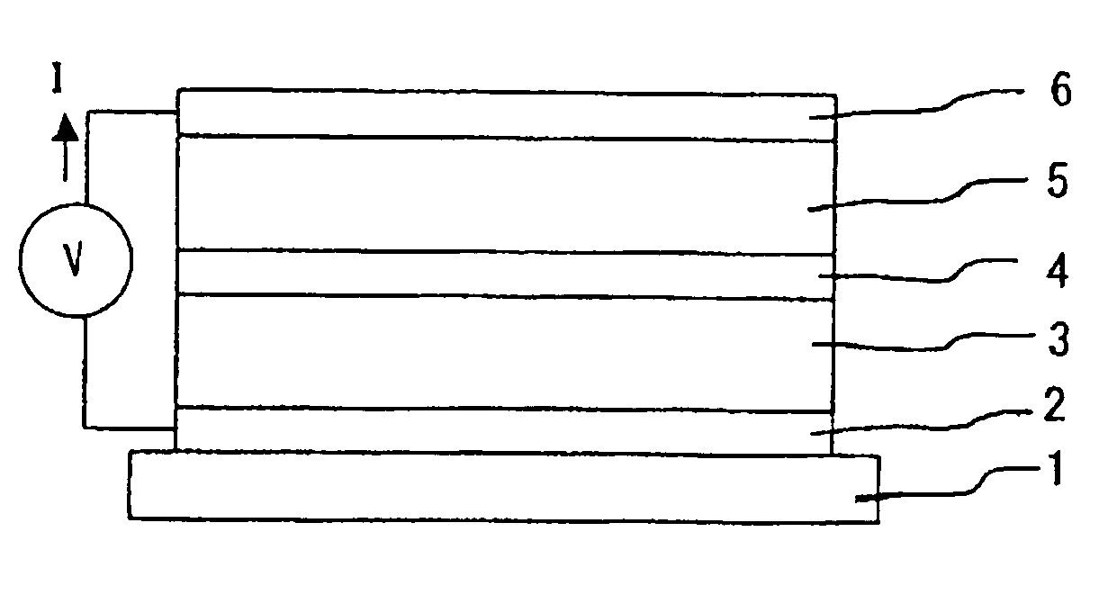
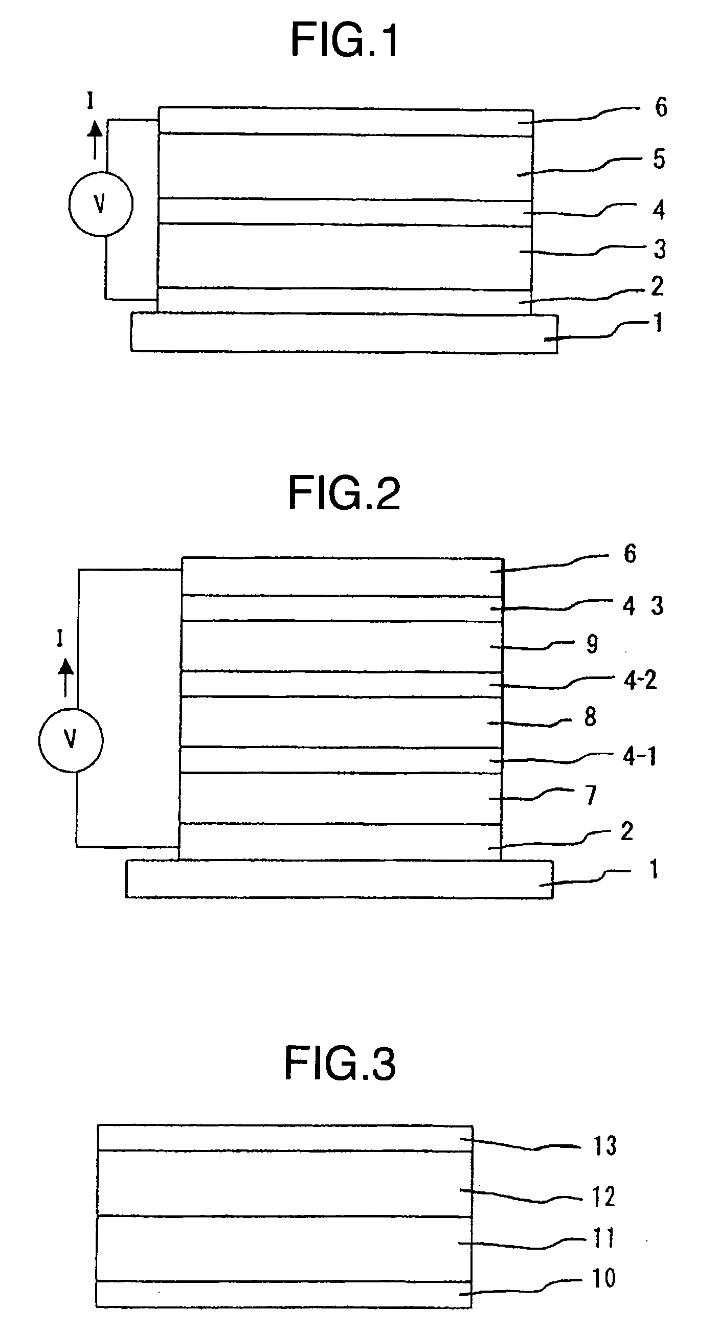
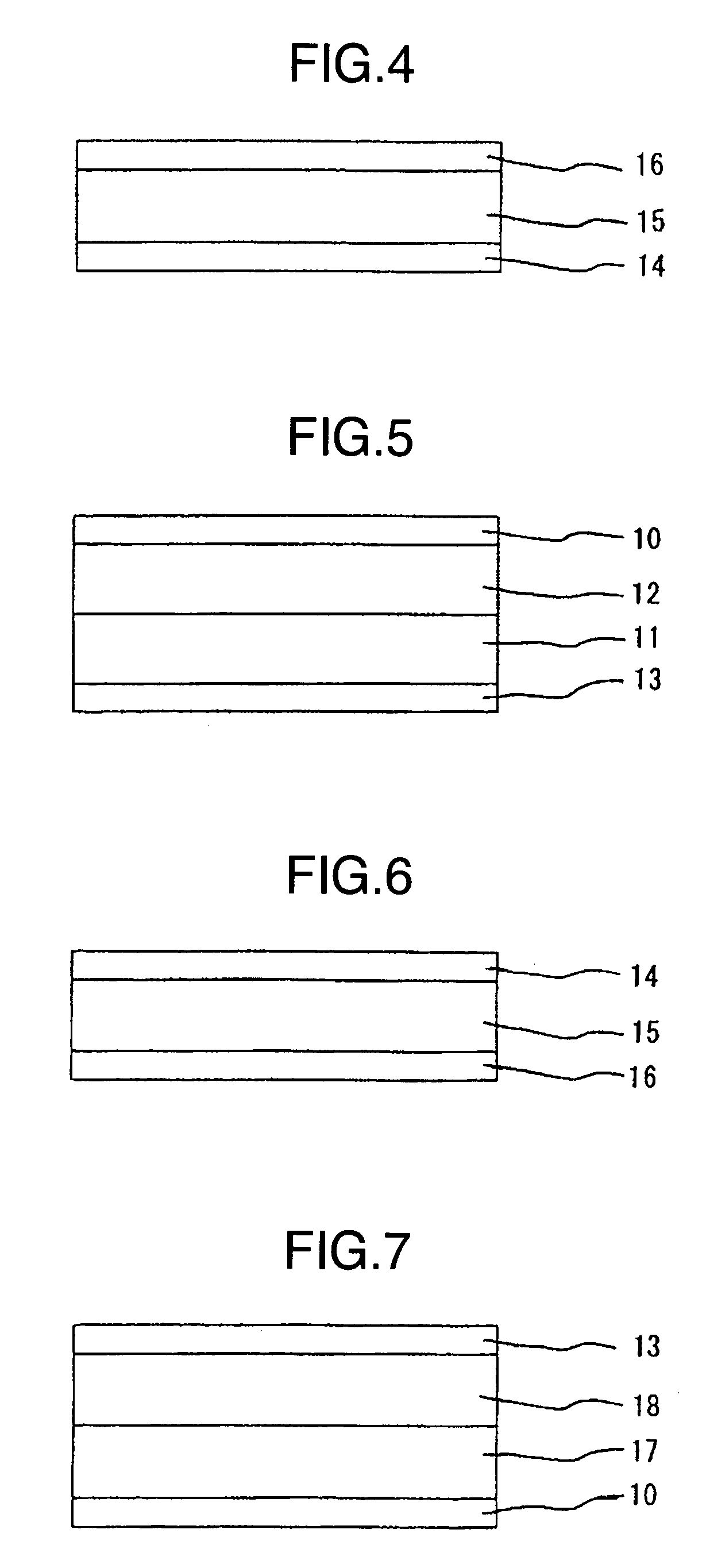
[0070] This embodiment relates to an organic light-emitting element, illustrated in FIG. 1, structured to emit light from the lower electrode side, and is described by referring to FIGS. 1, 3 and 4. FIG. 1 is a cross-sectional view of the organic light-emitting element of this embodiment. Referring to FIG. 1, the organic light-emitting element comprises the board 1 which supports the lower electrode 2, light-emitting unit 3, charge-generating layer 4, light-emitting unit 5 and upper electrode 6, wherein the charge-generating layer 4 is provided between the light-emitting units 3 and 5.

[0071] The board 1 can be made of a transparent material, e.g., quartz, glass or plastic (e.g., polyester, polymethyl methacrylate, polycarbonate or polysulfone), formed into a film, sheet or the like.

[0072] The lower electrode 2 formed on the board 1 worked as the anode in EXAMPLE 1. It can be made of a transparent, electr...

example 2

[0090] This embodiment relates to an organic light-emitting element, illustrated in FIG. 1, structured to emit light from the upper electrode 6 side, and is described by referring to FIGS. 1, 5 and 6. FIG. 1 is a cross-sectional view of the organic light-emitting element of this embodiment. The element comprises the board 1 which supports the lower electrode 2, light-emitting unit 3, charge-generating layer 4, light-emitting unit 5 and upper electrode 6, wherein the charge-generating layer 4 is provided between the light-emitting units 3 and 5.

[0091] The board 1 can be made of a transparent material, e.g., quartz, glass or plastic (e.g., polyester, polymethyl methacrylate, polycarbonate or polysulfone), formed into a film, sheet or the like.

[0092] The lower electrode 2 worked as the cathode in EXAMPLE 2. It was formed on the board 1, where about 10 mg of Al and 5 mg of a starting material for LiF, each put in a sublimation boat of molybdenum, were deposited in such a way to form t...

example 3

[0110] This embodiment relates to an organic light-emitting element, illustrated in FIG. 1, structured to emit light from the board 1 side, and is described by referring to FIGS. 1, 7 and 8, where a triplet material (phosphorescence-emitting material) is used as a light-emitting material. FIG. 1 is a cross-sectional view of the organic light-emitting element of this embodiment. Referring to FIG. 1, the organic light-emitting element comprises the board 1 which supports the lower electrode 2, light-emitting unit 3, charge-generating layer 4, light-emitting unit 5 and upper electrode 6, wherein the charge-generating layer 4 is provided between the light-emitting units 3 and 5.

[0111] The board 1 can be made of a transparent material, e.g., quartz, glass or plastic (e.g., polyester, polymethyl methacrylate, polycarbonate or polysulfone), formed into a film, sheet or the like.

[0112] The lower electrode 2 formed on the board 1 worked as the anode in EXAMPLE 3. It can be made of a transp...


PUM


Abstract

It is an object of the present invention to provide an organic light-emitting display of high light-emitting efficiency. The organic light-emitting element comprising a board, upper electrode, lower electrode, a plurality of light-emitting units placed between the upper and lower electrodes, and a charge-generating layer placed between a plurality of the light-emitting units, wherein one of the light-emitting units has a layer for emitting monochromatic light and one of the light-emitting units has a layer for emitting polychromatic light, the former unit having an equivalent or lower light-emitting efficiency than the latter unit.

Description

FIELD OF THE INVENTION [0001] The present invention relates to an organic light-emitting display. BACKGROUND OF THE INVENTION [0002] Recently, organic light-emitting displays have been attracting attention as planar displays of the next generation. These organic light-emitting displays have excellent characteristics, e.g., capacity of emitting white light, wide viewing angle and high-speed response. [0003] An organic electroluminescent element (hereinafter referred to as organic EL element) disclosed by JP-A-2003-272860 is known. FIG. 2 illustrates a conventional organic EL element. It comprises the board 1 which supports the lower electrode 2 and upper electrode 6, and light-emitting unit 7, charge-generating layer 4-1, light-emitting unit 8, charge-generating layer 4-2, light-emitting unit 9, charge-generating layer 4-3 which are placed between these electrodes 2 and 6. The light-emitting units 7, 8 and 9 are responsible for emitting red, green and blue light, respectively. The co...

Claims


Application Information

Patent Timeline
IPC IPC(8): G09F9/30H01J1/62H05B33/12H01J63/04H01L27/32H01L51/50H01L51/52H05B33/14H05B33/22
CPCH01L51/5016H01L51/5278H01L51/5036H10K50/11H10K2101/10H10K50/125H10K50/19
Inventor MASUDA, KAZUHITOISHIHARA, SHINGOARATANI, SUKEKAZUADACHI, MASAYA
Owner SAMSUNG DISPLAY CO LTD
Why Eureka
Try Eureka