Bearing of a telescopic connection

Inactive Publication Date: 2005-09-29
INA SCHAEFFLER KG
View PDF7 Cites 1 Cited by
  • Summary
  • Abstract
  • Description
  • Claims
  • Application Information

AI Technical Summary

Benefits of technology

[0042] The object of the invention is to provide a bearing of the generic type which has torsional strength, even in the case of h

Problems solved by technology

There are therefore already limits placed on the load-bearing capacity of the bearing per se on account of this small construction size.
Furthermore, because of the small construction size of the bearing, the elements of the bearing for play-free mounting cannot be subjected to unlimited load.
The torsional strength of the bearing before block abut

Method used


Image

  • Bearing of a telescopic connection
  • Bearing of a telescopic connection
  • Bearing of a telescopic connection

Examples


Example

DETAILED DESCRIPTION OF THE DRAWINGS

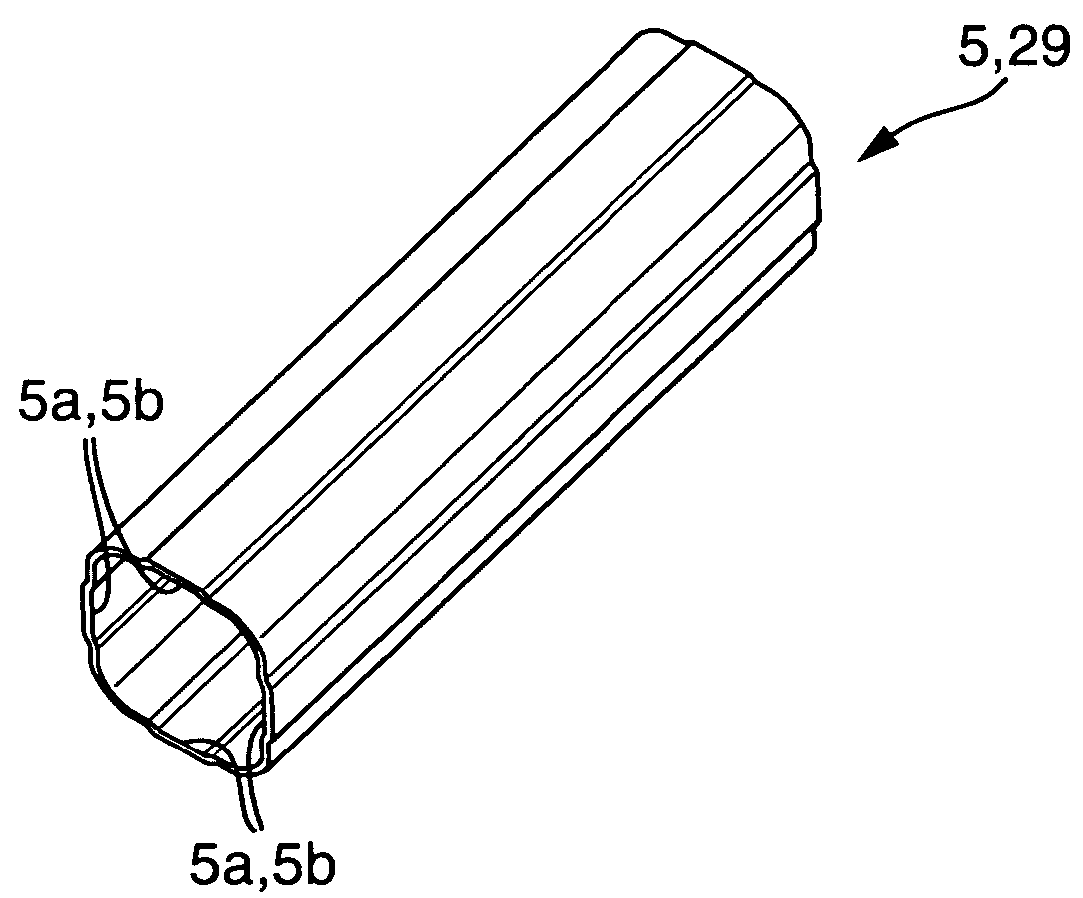
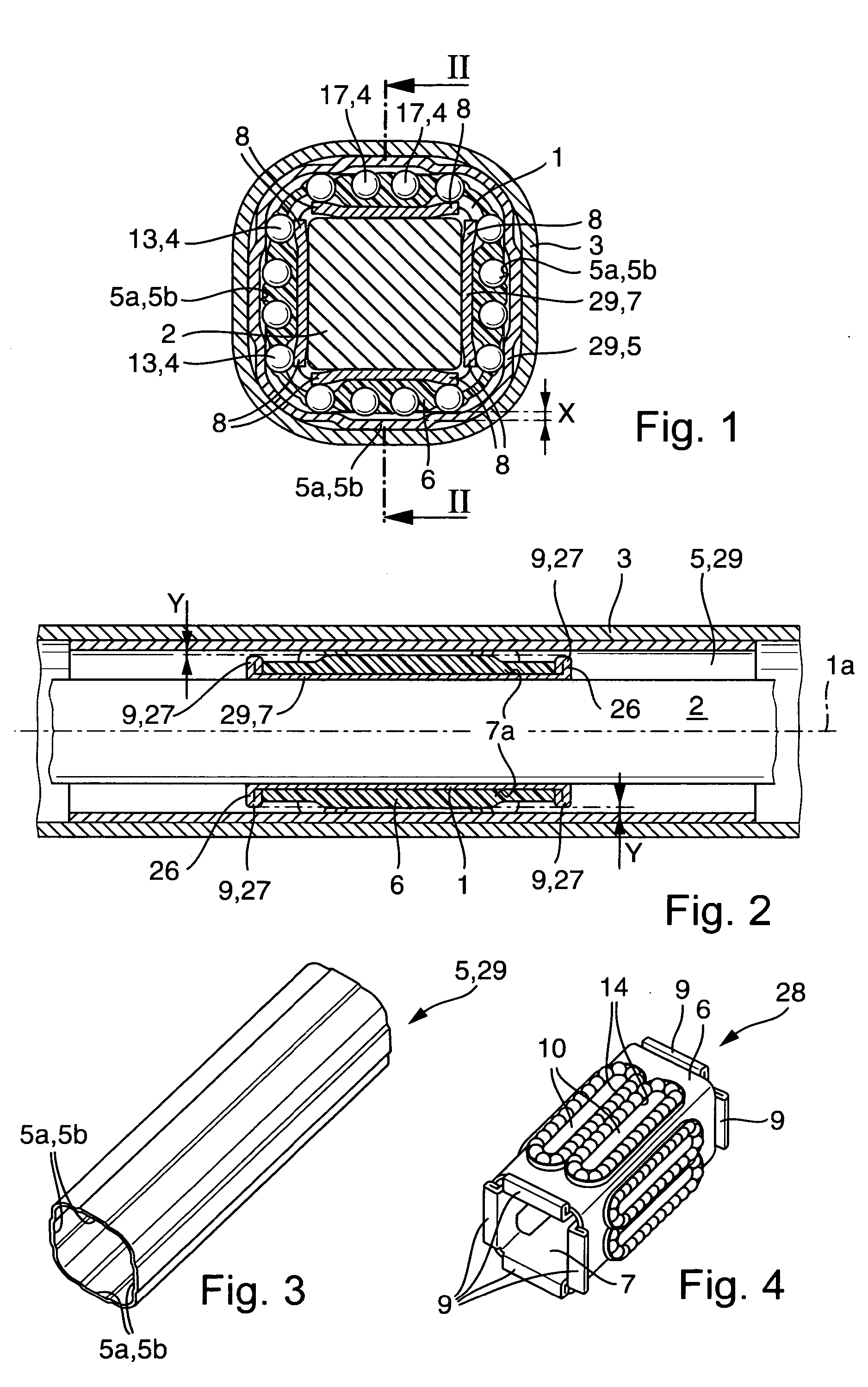
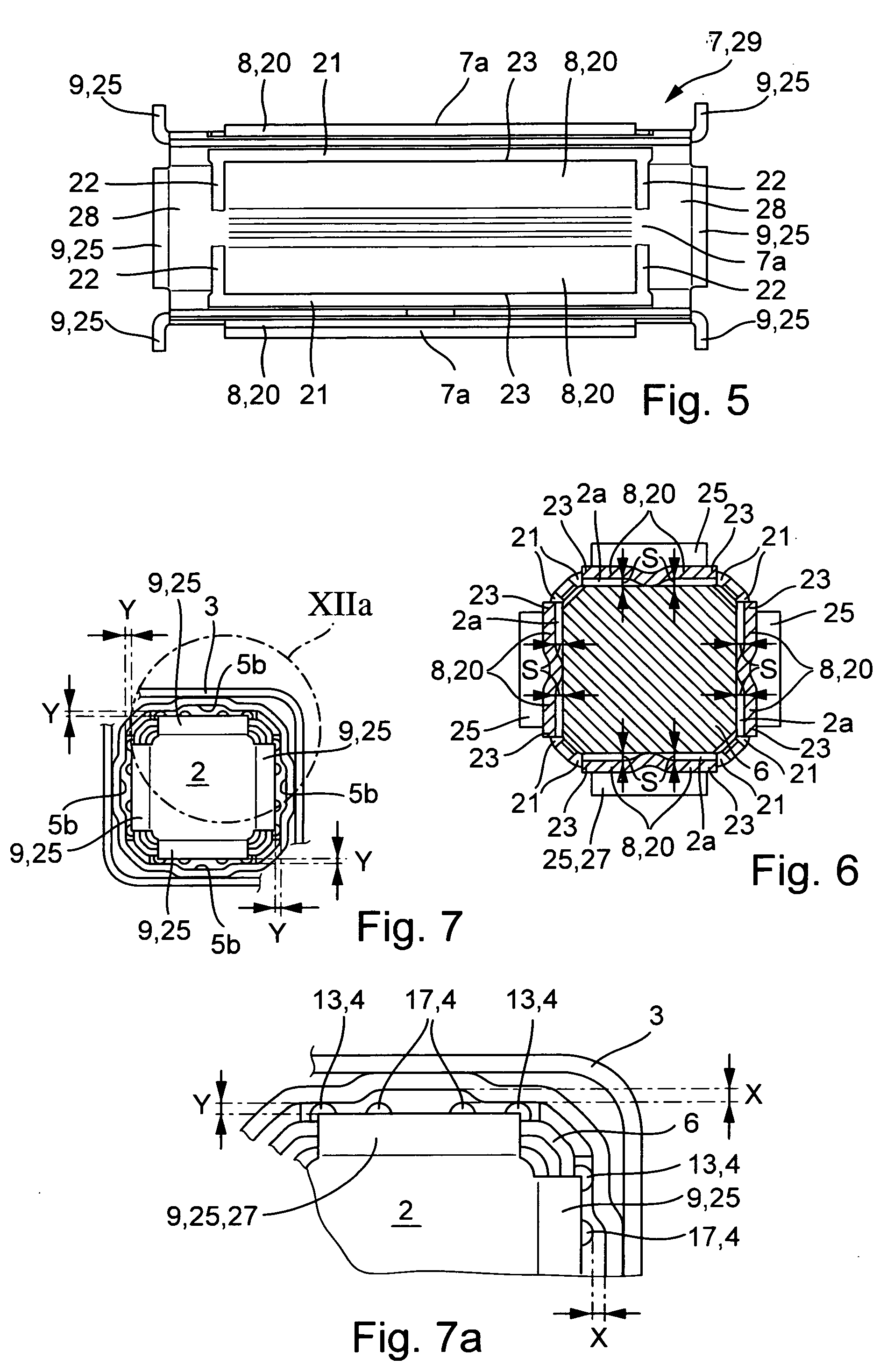
[0109] FIGS. 1 to 7 show an exemplary embodiment of a bearing 1 according to the invention in various views and also various individual parts of the bearing 1. FIG. 1 illustrates a cross section and FIG. 2 a longitudinal section through the bearing 1 between an inner profile 2 and an outer profile 3. The bearing 1 serves the longitudinally moveable mounting of the inner profile 2 and of the outer profile 3 on one another. The inner profile 2 and the outer profile 3 are moveable relative to one another along a longitudinal axis la of the bearing 1. Torques can be transmitted between the profiles 2 and 3 by means of a bearing 1. The bearing 1 consists of a sleeve 29 in the form of an outer sleeve 5, of a ball guide 6 and of a further sleeve 29 in the form of an inner sleeve 7. Furthermore, the bearing 1 has resiliently elastic elements 8 for compensating a bearing play in the bearing 1 and overload safeguards 9.

[0110] FIGS. 15 to 17 illustrate a b...


PUM


Abstract

A bearing (1, 30) for the longitudinally moveable mounting of an inner profile (2) and of an outer profile (3) on one another, the inner profile (2) and the outer profile (3) being moveable relative to one another along a longitudinal axis (1a, 30a) of the bearing (1, 30), and the bearing (1, 30) transmitting torques between the inner profile (2) and the outer profile (3), and, in the bearing (1, 30), a bearing play directed transversely with respect to the longitudinal axis (1a, 30a) being compensated elastically, with the result that the inner profile (2) and the outer profile (3) are prestressed relative to one another, free of the bearing play, by means of the bearing (1, 30), and, in this case, the profiles (2, 3) moved relative to one another transversely with respect to the longitudinal axis (1a, 30a) and supported on resiliently elastic elements (8) transversely with respect to longitudinal axis (1a, 30a) being freely moveable in relation to one another, at least by the amount of an operating play at the narrowest point between the outer profile (3) and the inner profile (2), and the inner profile (2) and the outer profile (3) being supported relative to one another at an overload safeguard (9) after the operating play has been overcome.

Description

FIELD OF INVENTION [0001] The invention relates to a bearing for the longitudinally moveable mounting of an inner profile and of an outer profile one on the other, the inner profile and the outer profile being moveable relative to one another along a longitudinal axis of the bearing, and the bearing transmitting torques between the inner profile and the outer profile, the bearing being with [0002] a sheet-metal outer sleeve arranged on the inside in the outer profile and between the outer profile and balls and fixed with respect to the outer profile, [0003] at least one ball guide having orbital ball raceways, [0004] resiliently elastic elements for the compensation of bearing plays, and [0005] an overload safeguard arranged between the outer profile and the inner profile, and, at the same time, each of the orbital ball raceways consisting of [0006] a row of balls, [0007] a longitudinal guide having a loaded subset of the balls of the row, [0008] a return guide having a first non-l...

Claims


Application Information

Patent Timeline
IPC IPC(8): F16C3/035F16C29/06F16D3/06
CPCF16C3/035F16D3/065F16C29/0697
Inventor FICK, MATTHIASSCHROK, JOCHENBAIER, RICHARDRADINGER, NORBERTZERNICKEL, ALEXANDER
Owner INA SCHAEFFLER KG
Why Eureka
Try Eureka