Slot lock for a cart

a slot lock and cart technology, applied in the field of slot locks, can solve the problem of inconvenient use of conventional slot locks

Inactive Publication Date: 2005-10-20
WU WEN CHIU
View PDF2 Cites 5 Cited by
  • Summary
  • Abstract
  • Description
  • Claims
  • Application Information

AI Technical Summary

Problems solved by technology

However, in the conventional slot lock, the releasing movement of the coin is not enough, such that the user always must pull the coin out of the slot with large force and the use of the conventional slot lock is inconvenient.

Method used


Image

  • Slot lock for a cart
  • Slot lock for a cart
  • Slot lock for a cart

Examples


Embodiment Construction

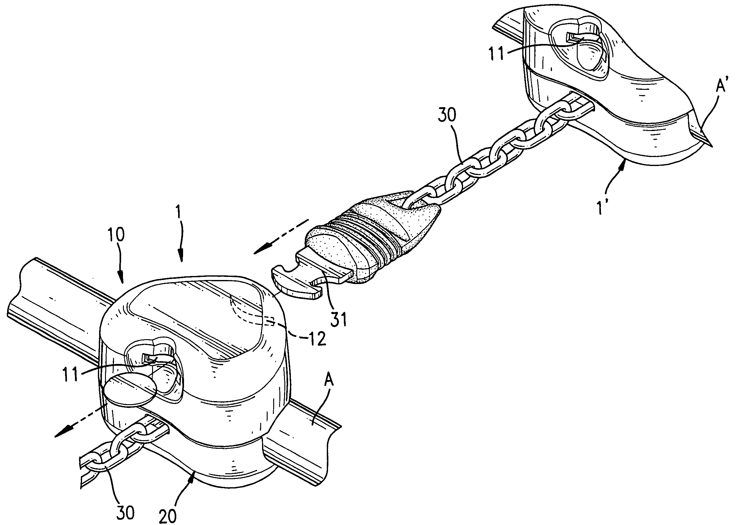
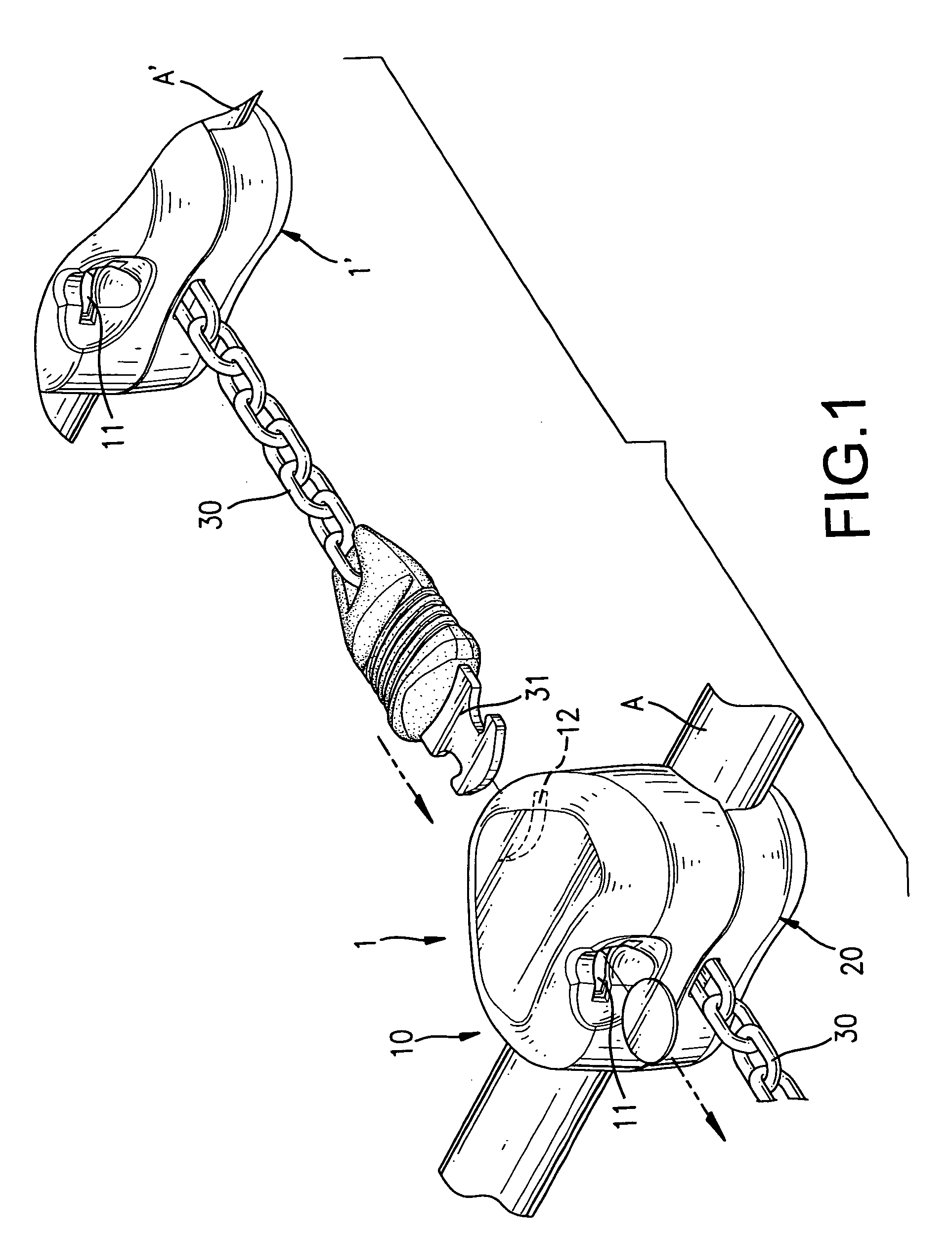
[0017] With reference to FIGS. 1 to 3, a slot lock for a cart in accordance with the present invention comprises a housing (1), a key (31) and a locking device (40). The housing (1) is attached to a handle (A) of the cart and comprises an upper shell (10) and a lower shell (20). The upper shell (10) has two ends, a slot (11) defined in one end and a key hole (12) defined in the other end and corresponding to the slot (11). The lower shell (20) is combined with the upper shell (10) by bolts (21). Each shell (10,20) has two sides provided respectively with a recess (13,23) to hold the handle (A) in cooperation.

[0018] The upper shell (10) further has a coin stand (14), a key stand (16), multiple posts (15), a partition wall (17) and two insert holes (18), as shown in FIG. 4. The coin stand (14) is formed in the upper shell (10) and corresponds to the slot (11) to hold a coin inserted into housing (1) through the slot (11). The key stand (16) is formed in the upper shell (10) and corre...


PUM


Abstract

A slot lock has a housing, a key and a locking device. The housing has an upper shell and a lower shell. The upper shell has a slot and a key hole. The locking device has two locking arms, a connecting arm, a first biasing member and a second biasing member. The locking arms are pivotally mounted in the upper shell and each has a key-clamping end, a tab and a coin-holding end. The connecting arm has two ends engaging respectively with the tabs on the locking arms. The first biasing member is mounted between the upper shell and the connecting arm and has two ends connected respectively to the locking arms. The second biasing member has two ends connected to the upper shell and a middle provided with a stop corresponding to the slot.

Description

BACKGROUND OF THE INVENTION [0001] 1. Field of the Invention [0002] The present invention relates to a slot lock, and more particularly to a slot lock for a cart. [0003] 2. Description of Related Art [0004] Carts are always arranged in super markets or shopping malls to assist customers to carry the selected objects they want and purchase. A slot lock is commonly mounted on a cart to connect multiple carts in series, such that an employee of a super market or shopping mall can manage the carts efficiently. The slot lock substantially comprises a housing, a locking device, a chain and a key. The housing has a slot and a key hole defined respectively in two ends of the housing. The locking device is mounted in the housing and corresponds to the slot and the key hole. The chain is attached to the housing, and the key is attached to the chain. To connect two carts with the slot lock, the key of the slot lock on one cart is inserted into the key hole and is held by the locking device of ...

Claims


Application Information

Patent Timeline
Patent Type & Authority Applications(United States)
IPC IPC(8): E05B27/06E05B29/14E05B31/00E05B35/00E05B65/00G07F5/00G07F5/02G07F7/06G07F11/00G07F13/00G07F15/00G07F17/00
CPCG07F5/02G07F7/0663G07F7/0654
Inventor WU, WEN-CHIU
Owner WU WEN CHIU
Why Eureka
Try Eureka