Method and apparatus for gantry crane sway determination and positioning

a technology of gantry cranes and sway determination, applied in the direction of cranes, load-engaging elements, transportation and packaging, etc., can solve the problems of collisions with other vehicles or objects, drivers are sometimes not able to steer cranes to the required accuracy, and the container handling yards are usually tightly packed

Inactive Publication Date: 2005-11-03
NOVARIANT
View PDF11 Cites 68 Cited by
  • Summary
  • Abstract
  • Description
  • Claims
  • Application Information

AI Technical Summary

Benefits of technology

[0010] A gantry crane system according to an embodiment of the present invention includes a frame structure having a plurality of vertical support legs and one or more members interconnecting predetermined pairs of the vertical support legs; and a positioning system including positioning sensors mounted to the frame structure and configured to receive positioning signals from positioning transmitters and a position processing unit configured to use the positioning signals to determine a deflection from vertical of at least one of the vertical support legs. In certain embodiments, the gantry crane system further includes a grappler assembly mounted to the frame structure. The position processing unit is configured to use positioning signals to determine a location of the grappler assembly.

Problems solved by technology

Container handling yards are usually tightly packed, and drivers are occasionally not able to steer cranes to required accuracies.
Vehicle maneuvering in such situations can delay the job that the driver is trying to do, and can even lead to collisions with other vehicles or objects.
Also, when a vehicle is driven off of the desired path, which is often made of reinforced concrete, damage can occur to the yard.
Consequently, considerable sway or deflection of the frame supports and members can occur.
This can lead to a significant difference (on the order of many inches) between the position of the top of the gantry crane and the wheels and, thus, inaccuracy in control.
Further, the GPS antennas are in an elevated position at the top of the crane, and the PCT publication does not take into account vehicle sway that can cause significant errors in determining the position of the wheels.
Also, when moving containers, sway in the vehicle or grappler can cause delays in container moving operations, or may even result in collision damage.

Method used


Image

  • Method and apparatus for gantry crane sway determination and positioning
  • Method and apparatus for gantry crane sway determination and positioning
  • Method and apparatus for gantry crane sway determination and positioning

Examples


Embodiment Construction

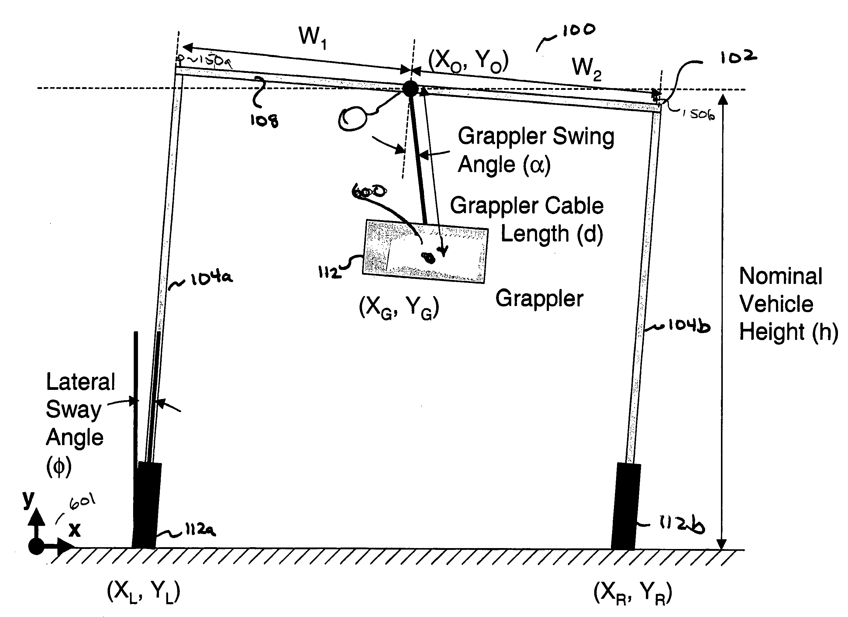
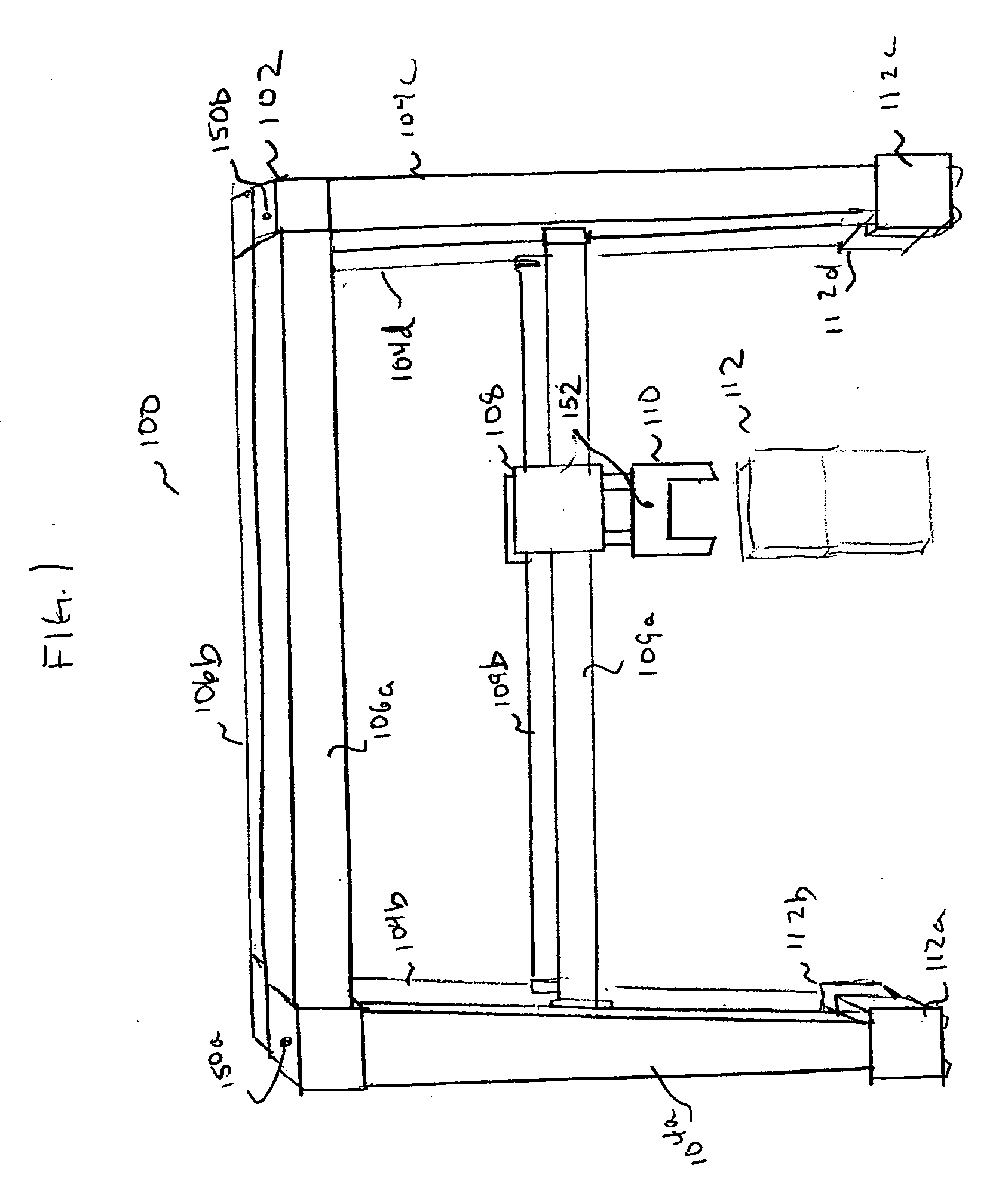
[0026] Turning now to the drawings and, with particular attention to FIG. 1, a gantry crane according to an embodiment of the present invention is shown and generally identified by the reference numeral 100. As shown, the gantry crane 100 includes a frame structure 102 having a plurality of vertical support members 104a-104d, and one or more interconnecting members 106a, 106b. A grappler assembly 108 is coupled to the frame 102 and is used to grasp, lift, and position containers 112. In the embodiment illustrated, the grappler assembly 108 includes horizontal members 109a, 109b, along which the grappler assembly 108 is moveable, and a grappler 110, suspended therefrom, and moveable vertically and horizontally.

[0027] In addition, in the embodiment illustrated, the gantry crane 100 is moveable on wheel assemblies 112a-112d, mounted at the ends of vertical members 104a-104d, respectively. In operation, the gantry crane 100 can be controlled to move into position to straddle and lift o...


PUM


Abstract

A gantry crane system includes a frame structure having a plurality of vertical support legs and one or more members interconnecting predetermined pairs of the vertical support legs; and a positioning system including positioning sensors mounted to the frame structure and configured to receive positioning signals from positioning transmitters and a position processing unit configured to use the positioning signals to determine a deflection from vertical of at least one of the vertical support legs. In certain embodiments, the gantry crane system further includes a grappler assembly mounted to the frame structure. The position processing unit is configured to use the positioning signals to determine a location of the grappler assembly.

Description

BACKGROUND OF THE INVENTION [0001] 1. Field of the Invention [0002] The present invention is directed generally to gantry crane systems and, particularly, to an improved system and method for gantry crane positioning. [0003] 2. Description of the Related Art [0004] In intermodal yards, ports, railyards, and other facilities (collectively referred to as “container handling yards”), shipping containers are typically handled by gantry cranes. Such gantry cranes usually have a frame with vertical support legs and one or more interconnecting and typically horizontal members. A hoisting system or grappler is usually mounted in a moveable and elevated position on the frame from one or more of the horizontal members. The crane may be equipped with wheels and a drive system to enable moving the crane around the container handling yard and to position the gantry crane over the container or stack of containers to be handled. The grappler may then be lowered to lift the container. [0005] Precis...

Claims


Application Information

Patent Timeline
Patent Type & Authority Applications(United States)
IPC IPC(8): B66C13/08B66C19/00
CPCB66C19/007B66C13/085
Inventor O'CONNOR, MICHAEL L.LAWRENCE, DAVID G.GROSS, AVI N.FRANTZ, ETHAN A.MELHORN, ROBERT C. JR.
Owner NOVARIANT
Why Eureka
Try Eureka