Battery charge testing apparatus

a battery charge and testing apparatus technology, applied in electrical testing, instruments, material analysis, etc., can solve the problems of difficult to distinguish the relative strength of light in bright daylight conditions, unsuitable for vision impaired or poor lighting conditions,

Inactive Publication Date: 2005-11-17
SUTHERLAND JOHN
View PDF16 Cites 2 Cited by
  • Summary
  • Abstract
  • Description
  • Claims
  • Application Information

AI Technical Summary

Benefits of technology

[0004] With the above described method and the battery charge testing apparatus, as described above, the person testing the battery receives a tactile or auditory sensation. The person can determine the strength of the charge of the

Problems solved by technology

A drawback of such a tester is that there can sometimes be difficulty in distinguishing the relative strength of the light in bright day

Method used


Image

  • Battery charge testing apparatus
  • Battery charge testing apparatus

Examples


Embodiment Construction

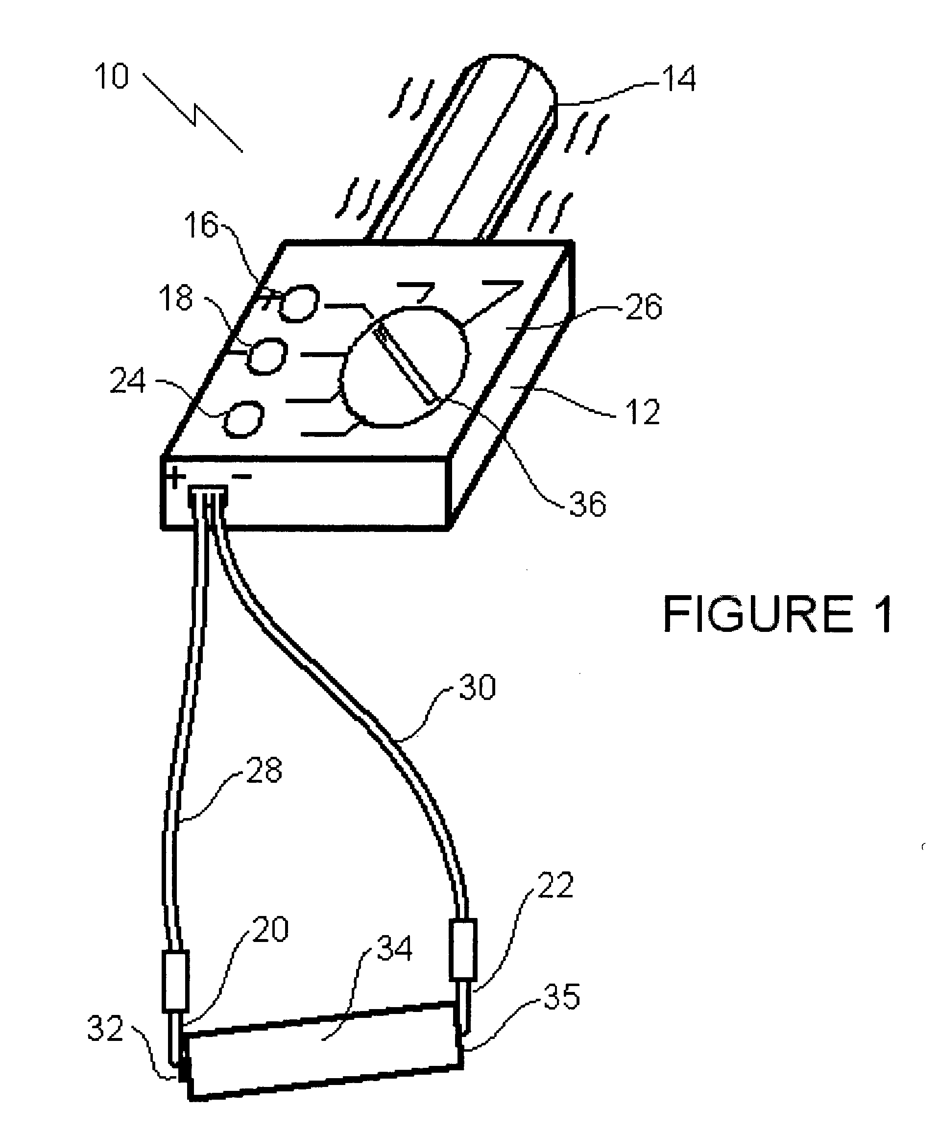
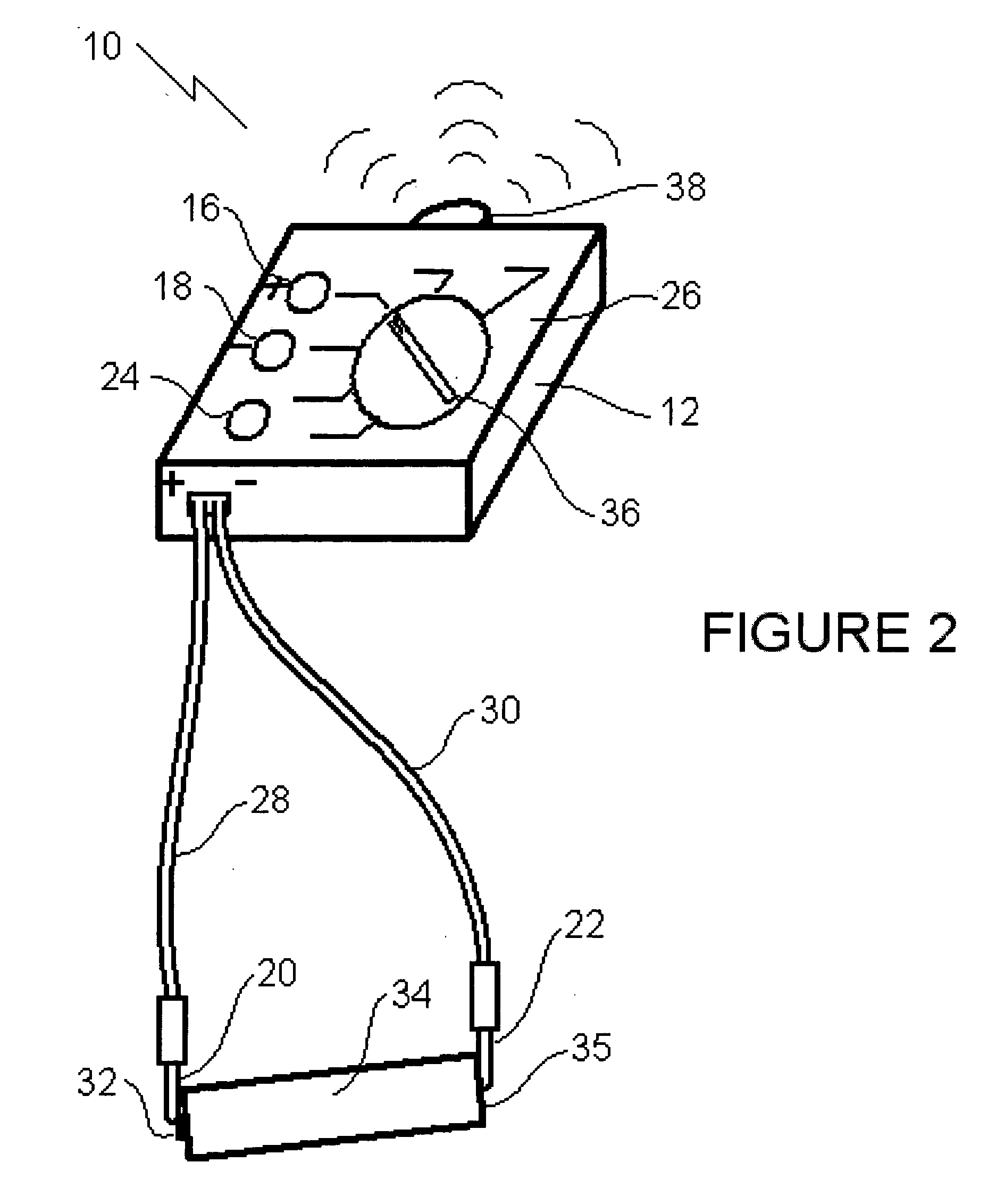
[0008] The preferred embodiment, a battery charge testing apparatus generally identified by reference numeral 10, will now be described with reference to FIGS. 1 and 2.

[0009] Structure and Relationship of Parts:

[0010] Referring now to FIG. 1, there is shown battery charge testing apparatus 10.

[0011] Battery charge testing apparatus 10 comprises a body 12 with a vibrator 14 mounted to body 12. An electrical circuit (not shown) is in body 12 to supply power to vibrator 14. External contacts 16, 18, 20, 22, and 24 are connected to the electrical circuit. External contacts 16 and 18, which may be referred to as a first and second contact, respectively, are positioned on an external surface 26 of body 12. External contacts 20 and 22, which may also be referred to as a first and second contact, respectively, are positioned on a first umbilical cord 28 extending from body 12 and a second umbilical cord 30 extending from body 12, respectively. When either first external electrical contac...


PUM


Abstract

A method and apparatus for testing a charge of a battery. The battery which is to be tested is connected to a device which generates at least one of tactile vibrations or auditory vibrations. A magnitude of a charge of the battery is determined by a magnitude of vibrations generated.

Description

FIELD OF THE INVENTION [0001] The present invention relates to a testing apparatus which may be used to determine whether a battery is adequately charged. BACKGROUND OF THE INVENTION [0002] There are various battery charge testing apparatus which provide a visual indication as to whether a battery is adequately charged. U.S. Pat. No. 2,081,656 (Anthony 1937) discloses a carton for holding batteries, which was developed so that the batteries could be tested without removing them from the carton. The battery charge testing apparatus illustrated for testing the batteries illuminates a light bulb. The intensity of light from the light bulb being indicative of the strength of the battery's charge. A drawback of such a tester is that there can sometimes be difficulty in distinguishing the relative strength of the light in bright daylight conditions. U.S. Pat. No. 1,337,160 (Reibeth 1920) discloses a battery charge testing apparatus having a needle, which moves along a scale to give an ind...

Claims


Application Information

Patent Timeline
IPC IPC(8): G01D7/00G01N27/416G01R31/36
CPCG01R31/3682G01D7/007G01R31/3646
Inventor SUTHERLAND, JOHN
Owner SUTHERLAND JOHN
Why Eureka
Try Eureka