Antenna array for an RFID reader compatible with transponders operating at different carrier frequencies

a technology of rfid reader and antenna array, which is applied in the field of rfid system, can solve the problems of large reading circuitry and programming complexity, and achieve the effect of reducing the number of antenna arrays

Active Publication Date: 2005-11-24
ASSA ABLOY AB
View PDF14 Cites 67 Cited by
  • Summary
  • Abstract
  • Description
  • Claims
  • Application Information

AI Technical Summary

Problems solved by technology

It is noted that the reader circuitry and programming are typically significantly larger and more complex than the RFID transponder due to the expanded functional requirements of the RFID reader in comparison to the RFID transponder.
Therefore, it is both highly desirable and a significant challenge to develop an RFID reader which is compatible with RFID transponders operating at either accepted carrier frequency and which achieves a level of performance comparable with an RFID reader optimized to operate at a single carrier frequency.

Method used


Image

  • Antenna array for an RFID reader compatible with transponders operating at different carrier frequencies
  • Antenna array for an RFID reader compatible with transponders operating at different carrier frequencies
  • Antenna array for an RFID reader compatible with transponders operating at different carrier frequencies

Examples


Embodiment Construction

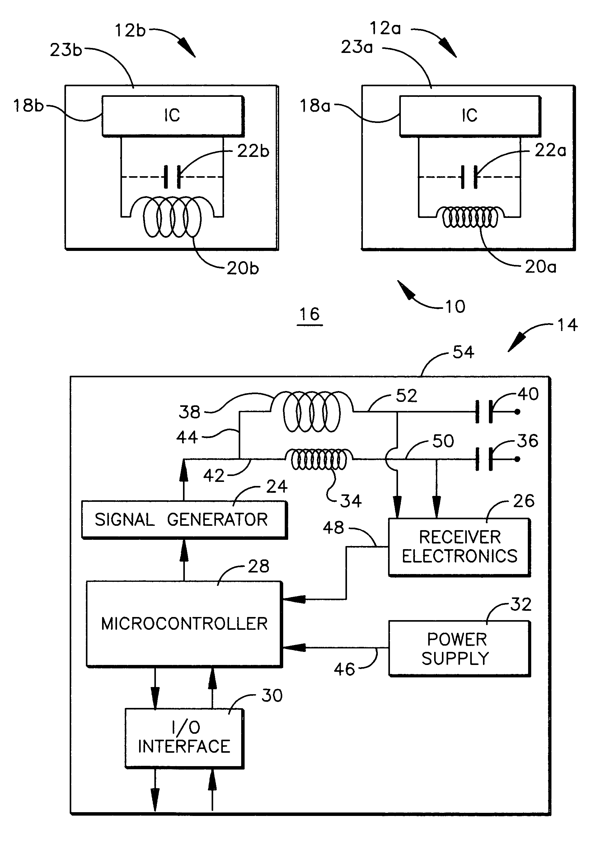
[0021] Referring initially to FIG. 1, a conceptualized RFID system is shown and generally designated 10. The RFID system 10 comprises a first RFID transponder 12a, a second RFID transponder 12b, and an RFID reader 14. The RFID reader 14 is a preferred embodiment of an RFID reader of the present invention and is described in greater detail hereafter.

[0022] The first and second RFID transponders 12a, 12b are passive devices, which are not physically coupled with an electrical power supply. The electrical power required to operate the first and second RFID transponders 12a, 12b is indirectly supplied to the first and second RFID transponders 12a, 12b by electromagnetic waves, which are periodically propagated through open space 16 to the first and second RFID transponders 12a, 12b from the RFID reader 14. Communication between the first and second RFID transponders 12a, 12b and the RFID reader 14 is only possible when the first and second RFID transponders 12a, 12b and RFID reader 14 ...


PUM


Abstract

An antenna array is provided for an RFID reader, which includes a first reader antenna tuned to operate at a first frequency and a second reader antenna tuned to operate at a second frequency different from the first frequency. The first and second antennas are preferably arranged in an overlapping arrangement or an opposing magnetic flux arrangement to reduce the effect of antenna self resonance.

Description

[0001] This a continuation-in-part application of Ser. No. 10 / 848,246 filed on May 18, 2004, which is incorporated herein by reference.TECHNICAL FIELD [0002] The present invention relates generally to RFID systems, and more particularly to an RFID reader for an RFID system, which has an array of non-interfering antennas tuned to different frequencies for communicating with a plurality of RFID transponders operating at different carrier frequencies. BACKGROUND OF THE INVENTION [0003] Radio frequency identification (RFID) systems generally consist of one or more RFID readers and a plurality of RFID transponders, which are commonly termed credentials. The RFID transponder is an active or passive radio frequency communication device, which is directly attached to or embedded in an article to be identified or otherwise characterized by the RFID reader, or which is alternatively embedded in a portable substrate, such as a card, keyfob, tag, or the like, carried by a person or an article t...

Claims


Application Information

Patent Timeline
Patent Type & Authority Applications(United States)
IPC IPC(8): G06K7/08H01Q5/10
CPCG06K7/10128G06K7/10356G06K7/10336G06K7/10316
Inventor QUAN, RALPH W.
Owner ASSA ABLOY AB
Why Eureka
Try Eureka