Low-electric-field emission end coil for wireless charging

A wireless charging and transmitter technology, applied in battery circuit devices, transformer/inductor circuits, circuits, etc., can solve problems affecting power transmission distance, location flexibility, and electrical transmission power limitations, to ensure near-field magnetic field effects , Minimize the generation of electric field, the effect of small electric field interference

Inactive Publication Date: 2017-06-13
苏州横空电子科技有限公司
View PDF3 Cites 3 Cited by
  • Summary
  • Abstract
  • Description
  • Claims
  • Application Information

AI Technical Summary

Problems solved by technology

[0011] The purpose of the present invention is to provide a low electric field transmitter coil for wireless charging, which aims to solve the problem that the traditional wireless charging

Method used


Image

  • Low-electric-field emission end coil for wireless charging
  • Low-electric-field emission end coil for wireless charging
  • Low-electric-field emission end coil for wireless charging

Examples


Embodiment Construction

[0026] In order to make the object, technical solution and advantages of the present invention more clear, the present invention will be further described in detail below in conjunction with the examples. It should be understood that the specific embodiments described here are only used to explain the present invention, not to limit the present invention.

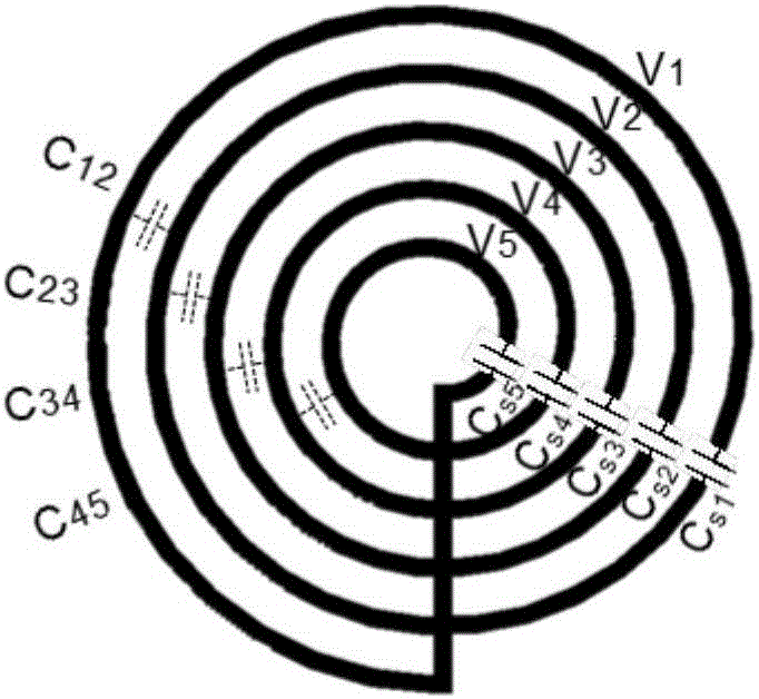
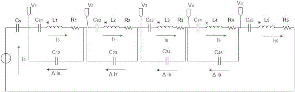
[0027] The low electric field transmitter coil for wireless charging provided by the embodiment of the present invention introduces between each single turn of the A4WP transmitter coil to reduce the negative impact of its own parasitic capacitance and reduce the radiation of EMI and RF interference (RFI) Interference tuning capacitor; the capacitance of the tuning capacitor makes the single-turn coil self-resonant, avoids the accumulation of AC voltage between adjacent coil turns, and minimizes the near-field magnetic field effect to generate electric field.

[0028] The present invention will be described in detail below ...


PUM


Abstract

The invention discloses a low-electric-field emission end coil for wireless charging. The low-electric-field emission end coil for wireless charging introduces tuning capacitors between single coil bodies of a common emission end coil, wherein the tuning capacitors are used for reducing adverse effects of parasitic capacitance of the tuning capacitors and reducing radiation interference of EMI and RF interference (RFI); the capacitance of the tuning capacitors makes the single coil bodies generate self resonance, avoids accumulation of alternating-current voltage between turn numbers of adjacent coils and makes a simultaneous minimum electric field of the near-field magnetic field effect generated. The low-electric-field coil is provided for resonant wireless charging product series, and has the advantages of being smaller in electric field interference, and capable of passing the FCC EMI certification more easily and providing a stable coil for large-area 1:N charging application.

Description

technical field [0001] The invention belongs to the technical field of wireless charging, and in particular relates to a low electric field transmitting coil for wireless charging. Background technique [0002] The A4WP-based wireless charging system works at 6.78MHz, and the coil design of its power transmitting end (PTU) usually requires a multi-turn spiral structure to meet the requirements of magnetic field consistency and coupling with the power receiving unit (PRU). The biggest challenge lies in the design of the coil, especially a coil with a large area. Since the accumulated parasitic capacitance will be larger compared to coils operating at low frequency or small size, the energy loss will also be greater. [0003] In the simple circuit model and equivalent parasitic capacitance of the wireless charging coil in the prior art, the equivalent parasitic capacitance C represents the sum of the parasitic capacitance between single turns of the coil, L represents the tot...

Claims


Application Information

Patent Timeline
IPC IPC(8): H02J50/12H02J50/70H01F27/42H01F38/14H02J7/00
CPCH01F27/42H01F38/14H01F2038/146H02J7/025
Inventor 林森
Owner 苏州横空电子科技有限公司
Why Eureka
Try Eureka