

Laser scanning microscope
a scanning microscope and laser technology, applied in the field of laser scanning microscopes, can solve problems such as the inability to excite multiple images
- Summary
- Abstract
- Description
- Claims
- Application Information
AI Technical Summary
Benefits of technology
Problems solved by technology
Method used
Image

Examples
first embodiment
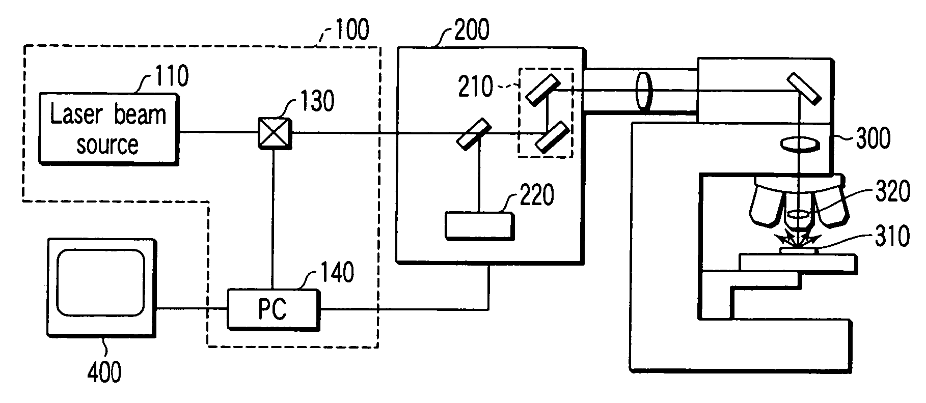
[0055]FIG. 9 is a diagram showing a configuration of a main part of a laser microscope according to a first embodiment of the present invention. In FIG. 9, the laser scanning unit 200 is omitted, and moreover, the microscope 300 is shown so as to be simplified. Note that this is the same in the following embodiments as well.
[0056] In the first embodiment, a beam expander 120 is disposed between the laser beam source 110 and the acousto-optic element 130 (which is may be an electro-optic element. Note that, in the following descriptions, in order to conveniently describe, both of an acousto-optic element and an electro-optic element are simply called “acousto-optic element”). With this configuration, eclipse of the laser beam by the opening of the acousto-optic device 130 is eliminated, and the power output loss of the laser beam by eclipse is eliminated. In addition, the intensity distribution of the emitted beam can be kept equivalent with that of the input beam by adjusting the b...
second embodiment
[0057]FIG. 10 is a diagram showing a configuration of a main part of a laser microscope according to a second embodiment of the present invention. In FIG. 10, same portions which are the same as those of FIG. 9 are denoted by the same reference numerals. In the second embodiment, a beam shaping device 150 using concave mirrors is added as a laser beam shaping device to the configuration of the first embodiment. In this way, the second embodiment has the feature that the laser beam shaping device is disposed downstream of laser output (i.e., between the laser beam source and the beam expander). Hereinafter, the necessity of the laser beam shaping device will be described.
[0058] First, a cross-sectional shape of a normal output light from the laser beam source (i.e., a beam shape) will be schematically described with reference to FIG. 11.
[0059]FIG. 11 is shows an internal configuration of the pulsed laser which can change the wavelength used as a laser light source of the multiphoto...
third embodiment
[0063]FIG. 12 is a diagram showing a configuration of a main part of a laser microscope according to a third embodiment of the present invention. Note that, in FIG. 12, same portions which are the same as those of FIGS. 9 and 10 are denoted by the same reference numerals. The third embodiment has the feature that the beam expander 120a is provided upstream of the acousto-optic element 130 and the beam expander 120b is provided downstream of the acousto-optic element 130.
[0064] The beam expander 120b provided downstream of the acousto-optic element 130 will be described. The beam diameter and the beam divergence angle of the laser beam suitably shaped by the beam expander 120a for acousto-optic device 130 may not be proper for the pupil diameter of the objective lens 320 in the microscope 300 and for improvement of the multiphoton excitation efficiency. Therefore, means for adjusting the beam diameter and the beam divergence angle of the laser beam after being emitted from the acous...
PUM
 Abstract
Description
Claims
Application Information