Air purifier and air purification method

a technology of air purifier and air filter, which is applied in the direction of auxillary pretreatment, heating type, separation process, etc., can solve the problems of lowering purification efficiency, affecting the degree of taking a long time to purify the entire installation area, so as to achieve uniform air pollution in the installation area. , the effect of free variation

Active Publication Date: 2005-12-08
SAMSUNG ELECTRONICS CO LTD
View PDF3 Cites 34 Cited by
  • Summary
  • Abstract
  • Description
  • Claims
  • Application Information

AI Technical Summary

Benefits of technology

[0010] The present invention has been made in view of these and / or other problems involved with the above-mentioned conventional air purifier, and one aspect of the present invention is to provide an air purifier, which can allow a free variation in a discharge direction of purified air, thereby making degree of air pollution of an installation area uniform.
[0011] It is another aspect of the present invention to provide an air purifier, which can reduce time for purifying the installation area, thereby enhancing purification efficiency.

Problems solved by technology

Accordingly, when indoor air is purified by the conventional air purifier as described above, there is a problem in that as the purified air is distributed mainly from the font side of the air purifier, the purified air is non-uniformly distributed depending on where the air purifier is positioned in an installation area, thereby making the degree of air pollution non-uniform in the installation area.
Furthermore, there is a problem in that, since the discharge of the purified air is concentrated in one direction, it takes a long time to purify the entire installation area, thereby lowering purification efficiency.

Method used


Image

  • Air purifier and air purification method
  • Air purifier and air purification method
  • Air purifier and air purification method

Examples


first embodiment

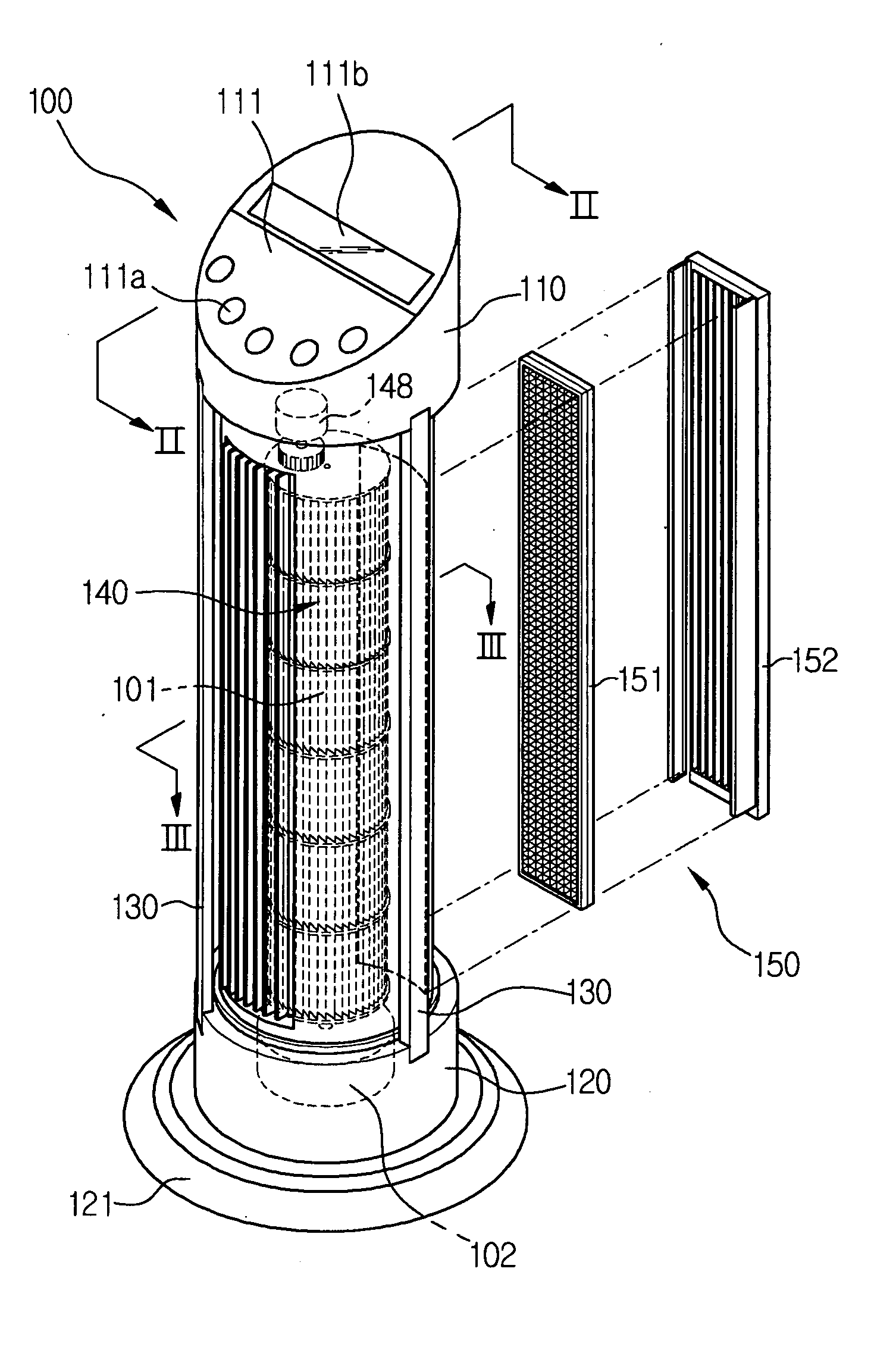
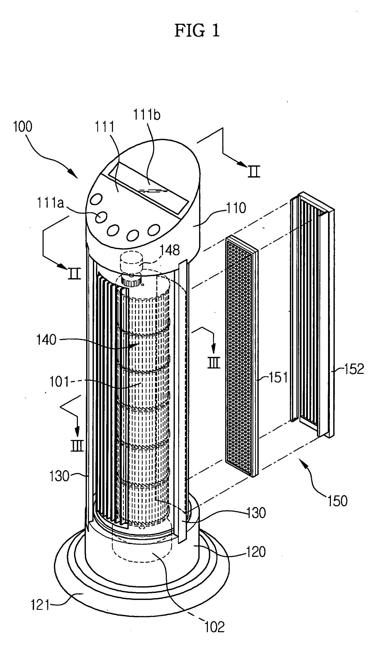
[0043] Operation of the air purifier is described below.

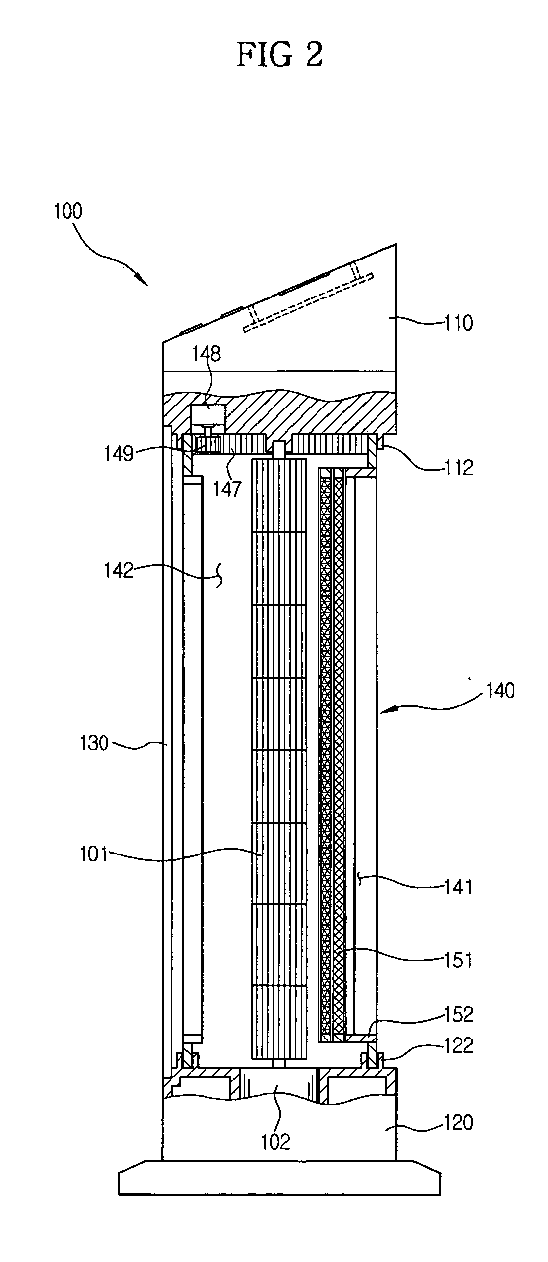
[0044] When starting the air purifier through the operation part 111, an airflow is generated with rotation of the axial flow fan 101. Air is inhaled through the intake grill, and filtrated through the filter 151, so that foreign substances in the air can be removed therefrom, providing purified air. The purified air is blown along the discharge flow path 142 by the axial flow fan 101.

[0045] Operation of the driving motor 148 to vary a blowing direction of air causes the entire rotating body 140 to rotate, changing the positions of the intake flow path 141 and the discharge flow path 142, so that the discharge direction of air is varied. According to control of the rotation by the driving motor 148, air can be discharged in all directions from the body 100, and the air contained in the installation area can be uniformly purified by continuously changing the discharge direction of the air.

second embodiment

[0046] An air purifier according to the present invention will be described in detail with reference to FIGS. 4 and 5 below.

[0047] The air purifier according to the second embodiment has the same configuration as that of the air purifier according to the first embodiment, except that the air purifier according to the second embodiment has a rotating body divided into two parts on upper and lower stages in order to more variously change the discharge direction of purified air.

[0048] The air purifier according to the second embodiment includes a cylindrical body 200 standing upright, as in the case of the air purifier according to the first embodiment, and a first and second rotating bodies 240 and 270, respectively, mounted on the upper and lower stages in the body 200.

[0049] The body 200 comprises an upper body 210 provided with an operation part 211 for controlling the air purifier, a lower body 220 provided with a fulcrum 222, an intermediate body 260 between the first and secon...

third embodiment

[0054] An air purifier according to the present invention will be described in detail with reference to FIGS. 6 and 7 as follows.

[0055] The air purifier according to the third embodiment is a modification of that of the second embodiment. The air purifier according to the third embodiment is the same as that of the air purifier according to the second embodiment in that first and second rotating bodies 340 and 370 are provided at upper and lower stages of the air purifier. However, there is a difference between the first and second embodiments in that the first rotating body 340 can rotate in relation to the second rotating body 370 below the first rotating body 340.

[0056] As shown in FIGS. 6 and 7, the air purifier according to the third embodiment includes a body 300 having an operation part 311 for controlling the air purifier and a fulcrum 322, and the first and second rotating bodies 340 and 370 mounted at the upper and lower stages in the body 300.

[0057] An axial flow fan 30...


PUM

PropertyMeasurementUnit
flow forceaaaaaaaaaa
driving forceaaaaaaaaaa
shapeaaaaaaaaaa

Abstract

An air purifier including: a filter which removes contaminants from air passing therethrough; a fan which generates a flow force to pass air through the filter; and a rotating body rotatably mounted in the air purifier and defining a flow path around the fan, a discharge direction of the flow path being varied by rotation of the rotating body.

Description

CROSS-REFERENCE TO RELATED APPLICATION [0001] This application claims the benefit of Korean Patent Application No. 2004-40001, filed on Jun. 2, 2004 in the Korean Intellectual Property Office, the disclosure of which is incorporated herein by reference. BACKGROUND OF THE INVENTION [0002] 1. Field of the Invention [0003] The present invention relates to an air purifier, and more particularly, to a freestanding air purifier in which a discharge direction of purified air can be varied. [0004] 2. Description of the Related Art [0005] Generally, a freestanding air purifier defines a flow path around an axial flow fan vertically mounted therein for intaking and discharging ambient air, and has a filter provided at an intake port for filtrating contaminants present in ambient air. This type of air purifier is referred to as a freestanding air purifier since its body has a vertically extended shape. [0006] In such a freestanding air purifier, a discharge port is formed at the opposite side ...

Claims


Application Information

Patent Timeline
Patent Type & Authority Applications(United States)
IPC IPC(8): B01D46/00B01D69/00B01D46/10B01D46/12B01D46/42F24F3/16
CPCB01D46/0021B01D2273/30B01D2265/05B01D46/10B01D46/60B01D69/00B01D46/12
Inventor HAN, JAE OHKIM, JIN BAEKCHOI, WEON SEOKLEE, JAI KWON
Owner SAMSUNG ELECTRONICS CO LTD
Why Eureka
Try Eureka