Striking tool with weight forward head

a technology of forward head and striking tool, which is applied in the field of hand-held striking tools, can solve the problems of not significantly insulate users from vibrations, prior art has generally not addressed the energy required to yield such devices, and prior art has similarly not addressed ways to manage overstrike, so as to reduce the effect of vibrations arising during use and better utilize the energy of users

Inactive Publication Date: 2005-12-22
ESTWING MFG
View PDF51 Cites 0 Cited by
  • Summary
  • Abstract
  • Description
  • Claims
  • Application Information

AI Technical Summary

Benefits of technology

[0009] Embodiments of the present invention provide a hand-held striking tool that significantly reduces the effect of vibrations arising during use. Embodiments of the present invention further provide a hand-held striking tool that better utilizes a user's energy. Embodiments of the present invention also provide a hand-held striking tool that manages the effect of overstrike.
[0010] One embodiment of the present invention provides a striking tool that includes a handle, a grip molded onto the handle, a generally curved shank connected to the handle, and a head connected to the shank, the head having a striking surface. The head defines a weight center. The handle may further include an elastomeric gasket that is positioned between the shank and the head. A pultruded rod may be positioned within the shank and the handle to provide additional strength to the striking tool.
[0011] Another embodiment of the present invention provides a striking tool that includes a handle, a grip molded onto the handle, a generally curved shank connected to the handle, and a head connected to the shank, the head having a striking surface. The head defines a weight center. The head includes an overstrike flange, the overstrike flange providing an area of contact should the striking surface hit beyond its target. The head may include a nail-pulling end that is distal to the striking surface. The head may further be generally curved to facilitate the function of the nail-pulling end. The handle may further include an elastomeric gasket that is positioned between the shank and the head. A pultruded rod may be positioned within the shank and the handle to provide additional strength to the striking tool.
[0012] The present invention also provides a hand-held striking tool having a reduced vibrational Shock Factor when compared to a hammer of the prior art. The hammer of this embodiment includes a handle, a grip molded onto the handle, a generally curved shank connected to the handle, and a head connected to the shank, the head having a striking surface. The head defines a weight center. The head includes an overstrike flange, the overstrike flange providing an area of contact should the striking surface hit beyond its target. The head may include a nail-pulling end that is distal to the striking surface. The head may further be generally curved to facilitate the function of the nail-pulling end. The handle may further include an elastomeric gasket that is positioned between the shank and the head. A pultruded rod may be positioned within the shank and the handle to provide additional strength to the striking tool.

Problems solved by technology

Typically, such prior art devices do not significantly insulate a user from the vibrations that result when the head of the hand-held impact tool strikes a surface.
While the prior art has attempted to address vibration reduction, the prior art has generally not addressed the energy required to yield such devices.
The prior art has similarly not addressed ways to manage overstrike.

Method used


Image

  • Striking tool with weight forward head
  • Striking tool with weight forward head
  • Striking tool with weight forward head

Examples


Embodiment Construction

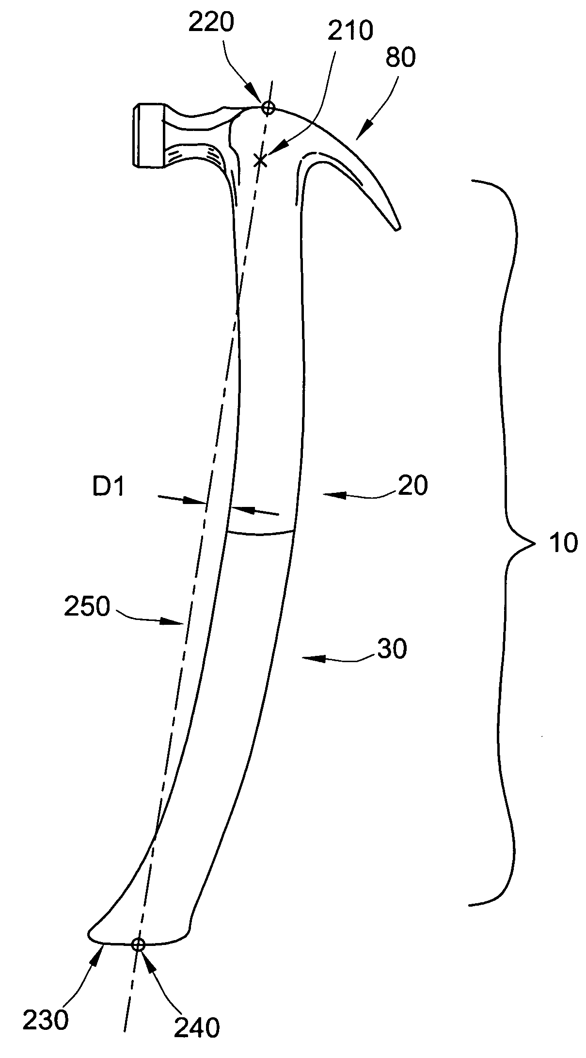
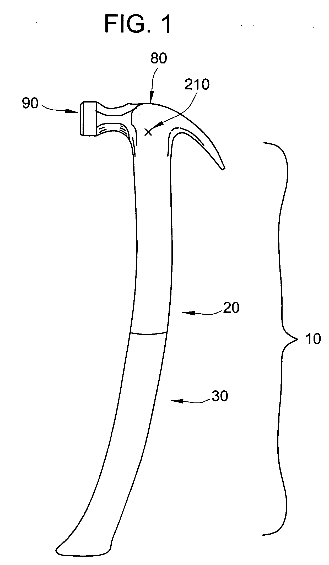
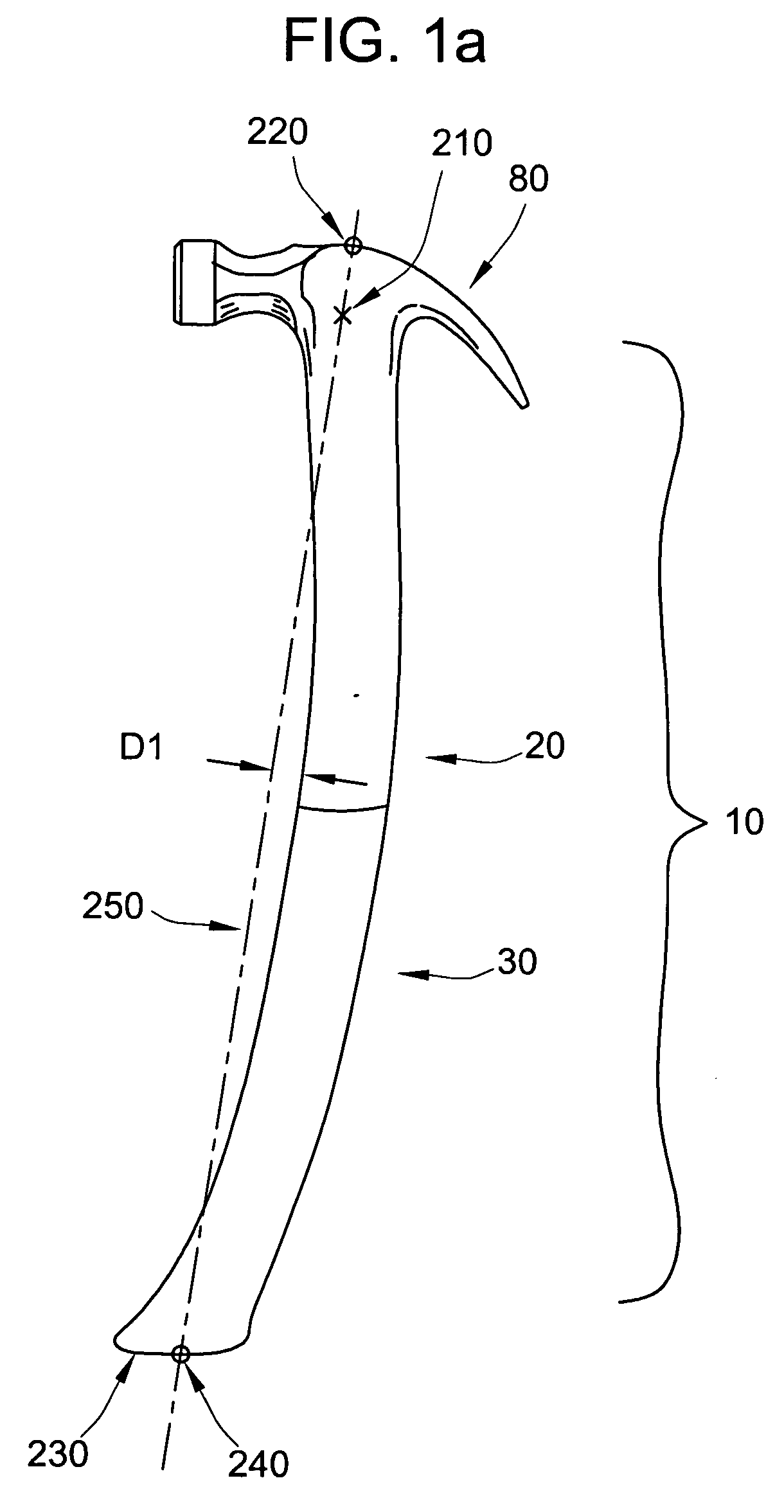
[0039] With reference to FIG. 1, there is provided according to one embodiment of the present invention a striking tool 10. The striking tool 10 includes a head 80 that includes a striking surface 90. The head may be metallic or made of other material useful for a striking tool head. For example, the head may be made of metal such as carbon steel and the like. Alternatively, the head may be made of a composite material. The striking tool 10 includes a curved handle 30 and a curved shank 20. The curved handle 30 and the curved shank 20 are adapted to be connected, one to the other. In an alternative embodiment, the curved handle 30 and the curved shank 20 are integrally formed so as to provide a unitary piece. The curved shank 20 and the head 80 are adapted to be attached, one to the other. The curved handle 30 and the curved shank 20 are generally curved so that the weight center 210 is positioned between the curved longitudinal centerline projected to bisect the head 80 (not shown)...


PUM


Abstract

The present invention provides a hand-held striking tool that has a head disposed forward of the centerline of a handle. The hand-held striking tool of the present invention may further include a flange positioned beneath the head of the tool, the flange functioning as a second area of contact so that the effect of overstrike may be controlled. The present invention also provides a hand-held striking tool that isolates the striking head of the tool from the handle such that the effect of vibrations caused by using the tool are reduced.

Description

CROSS-REFERENCE TO RELATED PATENT APPLICATIONS [0001] This application is a continuation of U.S. patent application Ser. No. 10 / 658,693, filed Sep. 9, 2003, which is a continuation of U.S. patent application Ser. No. 10 / 214,237, filed Aug. 7, 2002, now U.S. Pat. No. 6,647,829. The entire disclosures of each of the foregoing patent applications and the patent are hereby incorporated by reference herein.FIELD OF THE INVENTION [0002] The present invention relates to hand-held striking tools. The present invention further relates to hammers, axes and hatchets. BACKGROUND [0003] Hand-held striking tools are principally designed to deliver a blow to an object. Such tools are designed to drive nails, in the case of hammers, or chop and split wood in the cases of hatchets and axes. There are specialty impact tools, such as roofing striking tools, which have the physical characteristics of both a conventional striking tool and a conventional hatchet. There are also other specialty striking t...

Claims


Application Information

Patent Timeline
Patent Type & Authority Applications(United States)
IPC IPC(8): B25D1/00B25G1/01
CPCB25G1/01B25D1/00B25D1/12B25G1/102B26B23/00
Inventor YOUNGREN, ROBERT H.EISMAN, DANIEL M.LOVELAND, DANIELAISTON, CHRISTOPHERHARKINS, JACK
Owner ESTWING MFG
Why Eureka
Try Eureka