Broadside high-directivity microstrip patch antennas

a microstrip and patch antenna technology, applied in the direction of simultaneous aerial operations, antenna details, antennas, etc., can solve the problems of low antenna efficiency, small patch size, and inability to hold the required distance, so as to improve directivity, directivity of a single antenna, and large bandwidth

Active Publication Date: 2005-12-29
COMMSCOPE TECH LLC
View PDF39 Cites 25 Cited by
  • Summary
  • Abstract
  • Description
  • Claims
  • Application Information

AI Technical Summary

Benefits of technology

[0005] Several approaches can be found in the prior art, as for example a microstrip Yagi-array antenna [J. Huang, A. Densmore, “Microstrip Yagi Array Antenna for Mobile Satellite Vehicle Application”, IEEE Transactions on Antennas and Propagation, vol. 39, no 7, July 1991]. This antenna follows the concept of Yagi-Uda antenna where directivity of a single antenna (a dipole in the classical Yagi-Uda array) can be increased by adding several parasitic elements called director and reflectors. This concept has been applied for a mobile satellite application. By choosing properly the element spacing (around 0.35λo being λo the free-space wavelength), directivity can be improved.
[0006] However, this solution presents a significant drawback: if a substrate with a low dielectric constant is used in order to obtain large bandwidth, the patch size is larger than the above mentioned element spacing of around 0.35λo: the required distance can no longer be held. On the other hand, if a substrate with a high dielectric constant is used in order to reduce antenna size, the patch size is small and the coupling between elements will be insufficient for the Yagi effect function. In conclusions, although this may be a good practical solution for certain applications, it presents a limited design freedom.

Problems solved by technology

The problem of a microstrip array is that it is necessary to feed a large number of elements using a feeding network.
Such feeding network adds complexity and losses causing a low antenna efficiency.
However, this solution presents a significant drawback: if a substrate with a low dielectric constant is used in order to obtain large bandwidth, the patch size is larger than the above mentioned element spacing of around 0.35λo: the required distance can no longer be held.
On the other hand, if a substrate with a high dielectric constant is used in order to reduce antenna size, the patch size is small and the coupling between elements will be insufficient for the Yagi effect function.
In conclusions, although this may be a good practical solution for certain applications, it presents a limited design freedom.
The main practical problem of this solution is that several layers are needed yielding a mechanical complex structure.
However, the disadvantage of this solution is that the resonant frequency where the directivity performance is achieved can not be controlled unless one changes the patch size dimensions.

Method used


Image

  • Broadside high-directivity microstrip patch antennas
  • Broadside high-directivity microstrip patch antennas
  • Broadside high-directivity microstrip patch antennas

Examples


Embodiment Construction

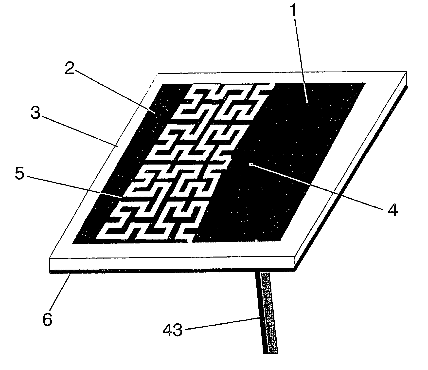
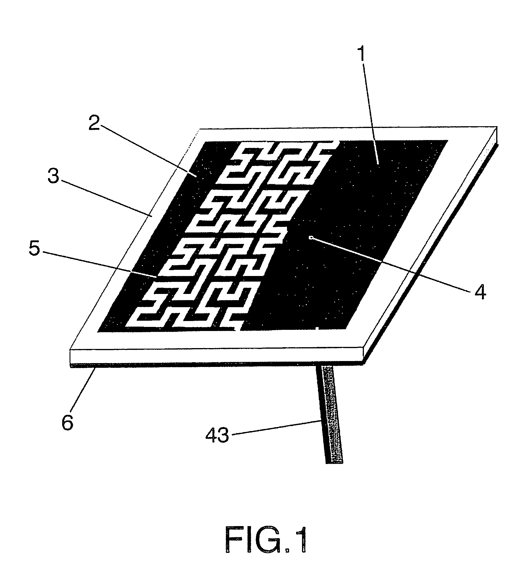
[0033]FIG. 1 shows a preferred embodiment of the high-directivity antenna formed by a driven patch (1) and a parasitic patch (2) placed on the same substrate (3) above a groundplane (6). The said driven patch (1) and parasitic patch (2) can be printed over a dielectric substrate (3) or can be conformed through a laser process. Any of the well-known printed circuit fabrication techniques can be applied to pattern patch surface over the dielectric substrate (3). Said dielectric substrate (3) can be for instance a glass-fibre board, a teflon based substrate (such as Cuclad®) or other standard radiofrequency and microwave substrates (as for instance Rogers 4003® or Kapton®).

[0034] The dielectric substrate (3) can even be a portion of a window glass of a motor vehicle if the antenna is to be mounted in a motor vehicle such as a car, a train or an airplane, to transmit or receive radio, TV, cellular telephone (GSM 900, GSM 1800, UMTS) or other communication services of electromagnetic wa...


PUM


Abstract

High-directivity microstrip antennas comprising a driven patch and at least one parasitic element placed on the same plane, operate at a frequency larger than the fundamental mode of the driven patch in order to obtain a resonant frequency with a high-directivity broadside radiation pattern. The driven patch, the parasitic elements and the gaps between them may be shaped as multilevel and/or Space Filling geometries. The gap defined between the driven and parasitic patches according to the invention is used to control the resonant frequency where the high-directivity behaviour is obtained. The invention provides that with one single element is possible to obtain the same directivity than an array of microstrip antennas operating at the fundamental mode.

Description

OBJECT OF THE INVENTION [0001] The present invention refers to high-directivity microstrip antennas having a broadside radiation pattern using electromagnetically coupled elements. A broadside radiation pattern is defined in the present invention as a radiation pattern having the maximum radiation in the direction perpendicular to the patch surface. [0002] The advantage of an antenna having a broadside radiation pattern with a larger directivity than that of the fundamental mode, is that with one single element it is possible to obtain the same directivity as an array of microstrip antennas operating at the fundamental mode, the fundamental mode being the mode that presents the lowest resonant frequency, but there is no need to employ a feeding network. With the proposed microstrip antenna, there are no losses due to the feeding network and therefore a higher gain can be obtained. BACKGROUND OF THE INVENTION [0003] The conventional mechanism to increase directivity of a single radia...

Claims


Application Information

Patent Timeline
Patent Type & Authority Applications(United States)
IPC IPC(8): H01Q1/36H01Q1/38H01Q5/00H01Q5/378H01Q5/385H01Q9/04
CPCH01Q1/36H01Q5/385H01Q5/378H01Q9/0407
Inventor PUENTE BALIARDA, CARLESPROS, JAUME ANGUERABORAU, CARMEN BORJA
Owner COMMSCOPE TECH LLC
Why Eureka
Try Eureka