
Toy vehicle flip/jump stunt device

Inactive Publication Date: 2005-12-29
MATTEL INC
View PDF8 Cites 51 Cited by
  • Summary
  • Abstract
  • Description
  • Claims
  • Application Information

AI Technical Summary

Benefits of technology

[0011] In accordance with the present invention, there is provided a flip/jump stunt device for use in combination with a toy vehicle and toy vehicle trackset, the stunt device comprising: a support base; a trackway segment support secured to the base; a track segment supported by the base having a proximate end; a frame supported by the base; a launcher pivotally support

Problems solved by technology

Such toy vehicle tracksets have evolved from simple closed loop track devices to relatively complex multiply curved and looped travel path sets.

Method used


Image

  • Toy vehicle flip/jump stunt device
  • Toy vehicle flip/jump stunt device
  • Toy vehicle flip/jump stunt device

Examples


Embodiment Construction

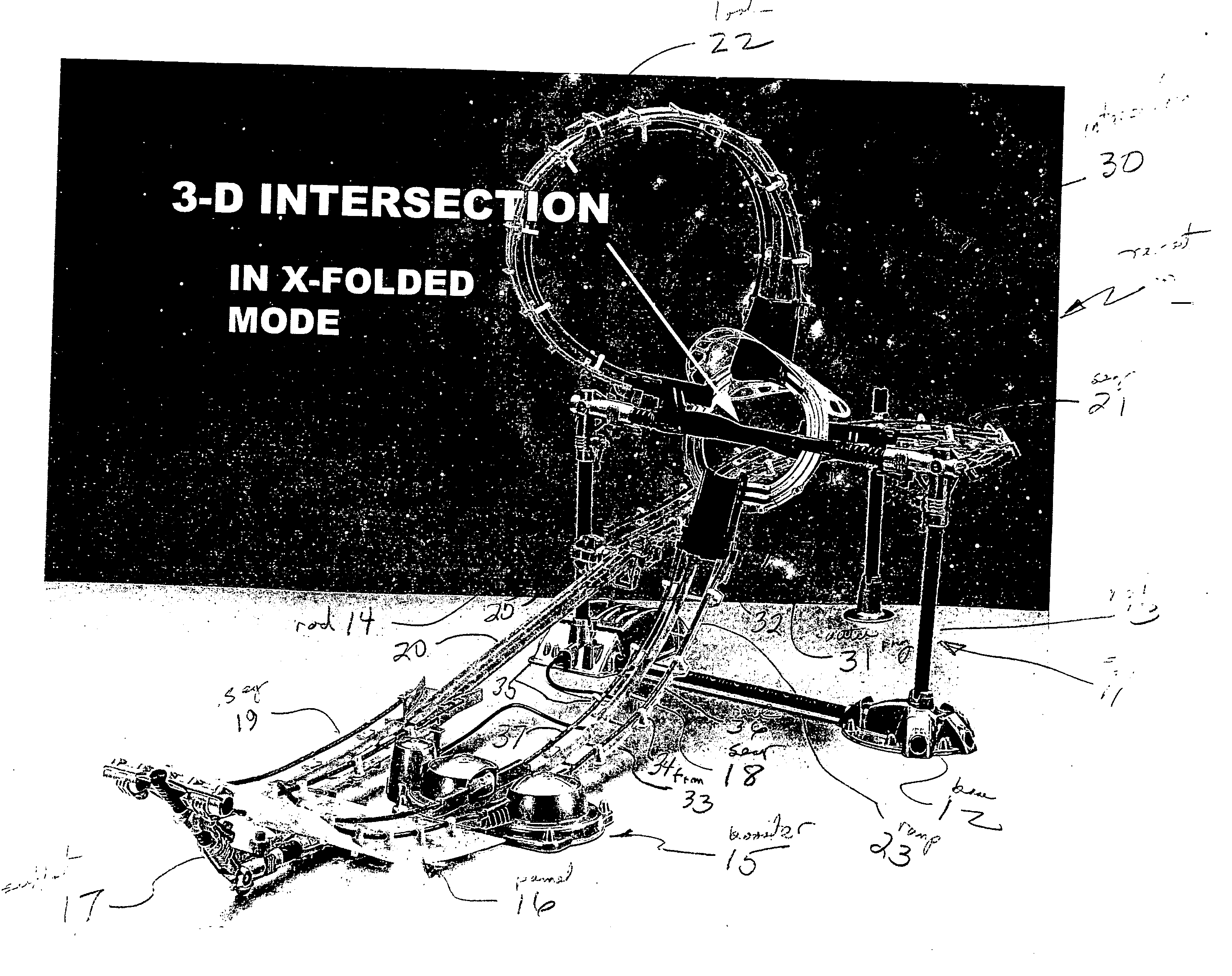
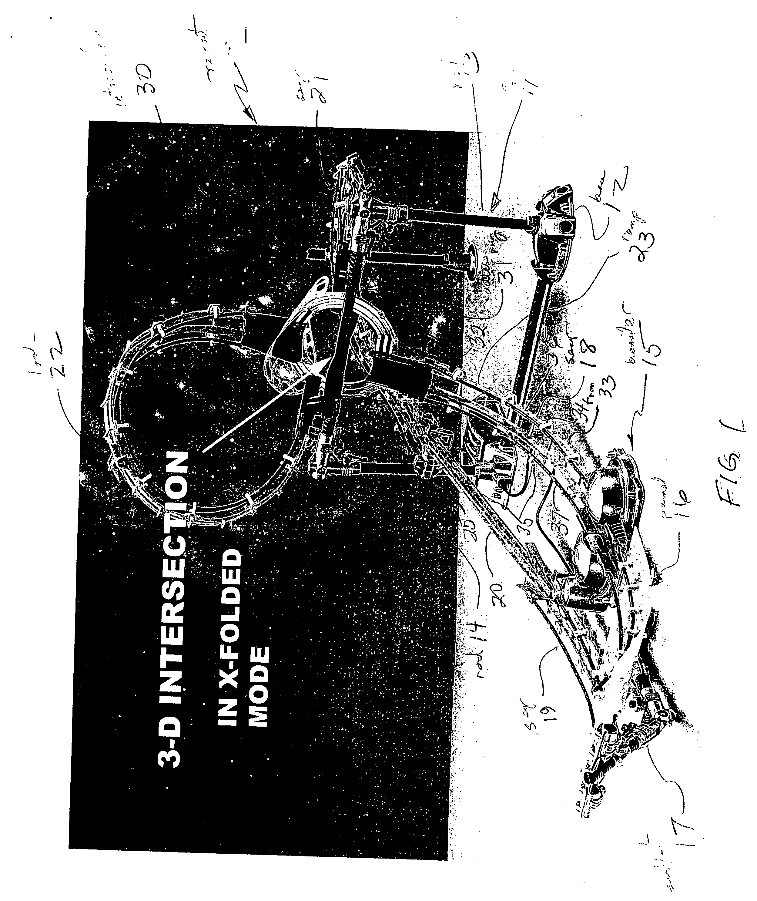
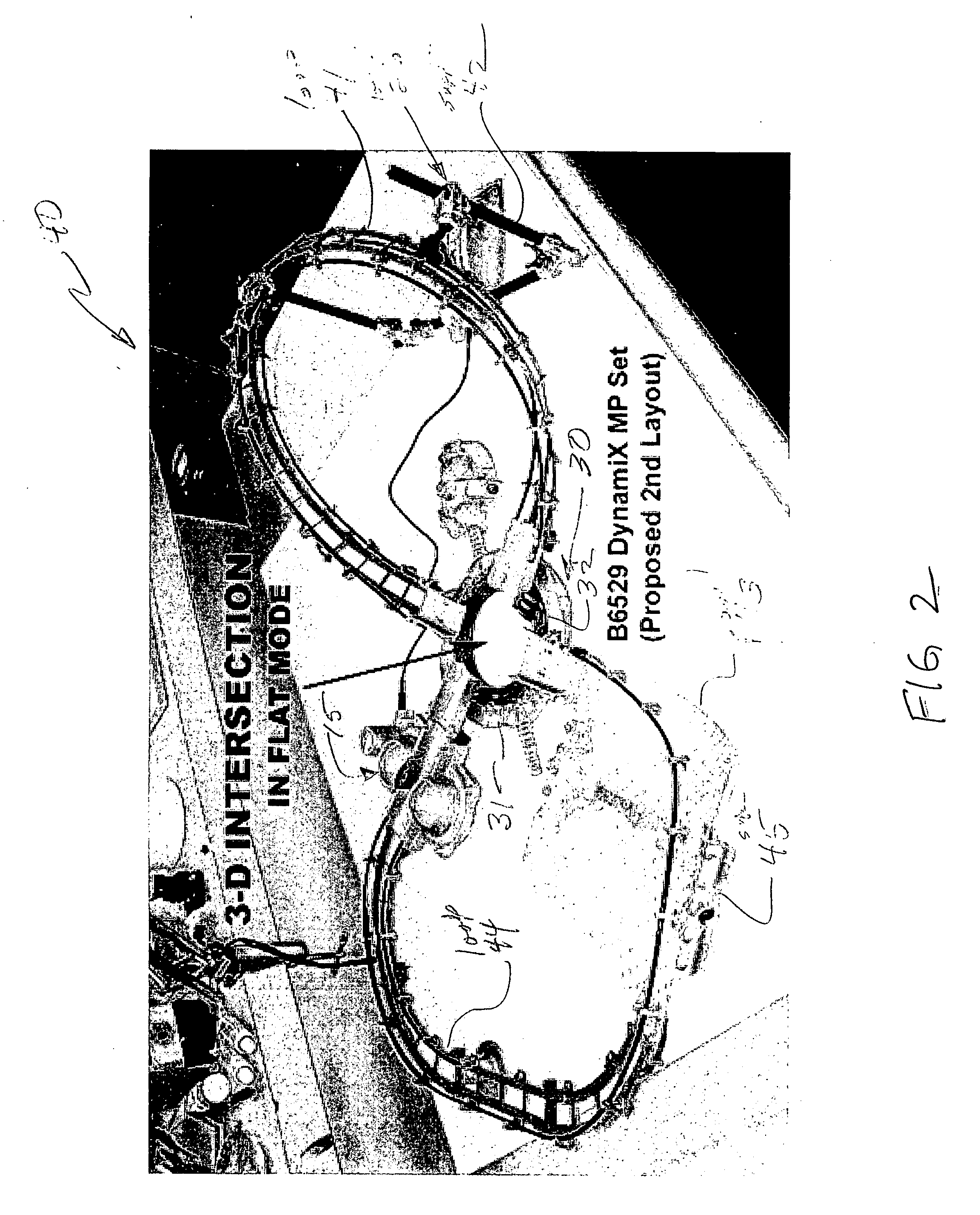
[0016] By way of overview, the present invention flip / jump device utilizes a supporting frame coupled to a track segment of a toy vehicle trackset. The supporting frame includes a pivotally supported launcher which is aligned with the track segment and which is capable of receiving a traveling toy vehicle. A spring mechanism is operative upon the launcher to pivot it rapidly in an upward direction when a latch and trigger release mechanism is actuated. The trigger and latch release mechanism is operated in response to the impact of a toy vehicle traveling from the coupled track segment onto the launcher element. Once the trigger is released, the energy stored within the spring mechanism rapidly pivots the launcher upon the frame thrusting the toy vehicle thereon in an upward and forward somersault travel path.

[0017]FIG. 1 sets forth a perspective view of a toy vehicle trackset constructed in accordance with the present invention and generally referenced by numeral 10. Toy vehicle t...


PUM


Abstract

The stunt device is positioned within the travel path of a toy vehicle and is supported by a support frame. A flip device is pivotally coupled to the frame and positioned to receive a toy vehicle from a portion of the trackset. A spring is coupled to the flip device and is restrained by the trigger. The trigger is positioned within the toy vehicle travel path upon the vehicle entrance to the stunt device. As the toy vehicle impacts the trigger, the spring is released causing the flip device to pivot rapidly thrusting the toy vehicle into the air in a somersault projection.

Description

CROSS-REFERENCE TO RELATED APPLICATIONS [0001] This application claims priority of Provisional Application 60 / 538,953 entitled TOY VEHICLE FLIP / JUMP STUNT DEVICE filed Jan. 23, 2004 on behalf of the applicants of the present application.FIELD OF THE INVENTION [0002] This invention relates generally to toy vehicle tracksets and particularly to stunt device utilized therein. BACKGROUND OF THE INVENTION [0003] Toy vehicle manufacturers have endeavored to provide toy vehicle tracksets which maximize the amusement and entertainment provided to the user. Such toy vehicle tracksets have evolved from simple closed loop track devices to relatively complex multiply curved and looped travel path sets. To further enhance the attractiveness of such toy vehicle tracksets, practitioners in the art have provided a variety of so-called stunt devices. Stunt devices vary substantially but usually include some type of toy vehicle movement or action. Typically, stunt devices have been provided which cau...

Claims


Application Information

Patent Timeline
IPC IPC(8): A63H18/00A63H18/02
CPCA63H18/028
Inventor SHELTMAN, DAVID A.POHLMAN, JOE K.FINIZZA, MICHAELMAYER, MARKANDREWS, MIKETAM, NELSON
Owner MATTEL INC
Learn More