
Chair back for a chair

a chair and back technology, applied in the field of chair backs, can solve the problems of limiting the shape of the bottom portion of the chair back, prior art chair backs or support devices however do not address the ability to attach fabric to a support frame, and prior art chair backs or support devices do not address the ability to attach fabric, etc., to achieve convenient removal and change of colour, easy installation, and thin profile

Active Publication Date: 2006-04-11
ALLSEATING CORPORAITON
View PDF16 Cites 68 Cited by
  • Summary
  • Abstract
  • Description
  • Claims
  • Application Information

AI Technical Summary

Benefits of technology

[0010]An object of one aspect of the present invention is to provide an improved chair back for a chair having a frame and a removable mesh knitted pocket or sleeve that can accommodate different shaped backs and is held in place on the chair frame via the tension within the knitted sock and the structure of the chair frame therefore not requiring fasteners.
[0014]Advantages of the present invention are: the arrangement of the removable elastomeric support sleeve with the support frame portion and the tensioning frame portion allows for the chair back to be a variety of shapes; no fasteners or mechanical attachments are required for attaching the removable elastomeric support sleeve to the frame portions; trim and / or covers are not required to hide fasteners; the elastomeric support sleeve is easily removable to change colour; easy to install in the field and for servicing; the tensioning and support frame portions can be shaped into various design chair backs; the defined shapes of the support frame and tensioning frame portions can be made from a variety of material such as metal tubing so long as the two frame portions can fit together; the removable elastomeric support sleeve may be shaped to accommodate both the tensioning frame portion and the support frame portion via an opening that is conveniently positioned at the widest point on the chair back shape and can accommodate a removable lumbar support; the tensioning of the removable elastomeric support sleeve for the chair back occurs automatically as soon as the tensioning frame portion and the support frame portion are locked together; and the structure of the support frame portion allows for support for the chair back to occur all the way to the mid-point of the chair back rather than from the chair base member thereby allowing the structure of the support frame portion to be partially made from a thinner tubing and therefore result in a thinner profile.

Problems solved by technology

As such, there are limitations as to the shape of the bottom portion of the chair back so as to avoid either having excess material at the bottom portion of the chair or not being able to fit the sleeve over the middle portion of the chair back if the bottom portion was smaller or narrower than the middle portion.
Prior art chair backs or support devices however do not address issues of attaching fabric to a support frame without fasteners, while applying the fabric to a variety of different shaped backs.
More specifically prior art devices do not address the ability for attaching a fabric on to a chair back that is shaped identically at both the top and bottom of the chair back therefore not requiring that the bottom of the chair back be a place for the attachment of the fabric.

Method used


Image

  • Chair back for a chair
  • Chair back for a chair
  • Chair back for a chair

Examples


Embodiment Construction

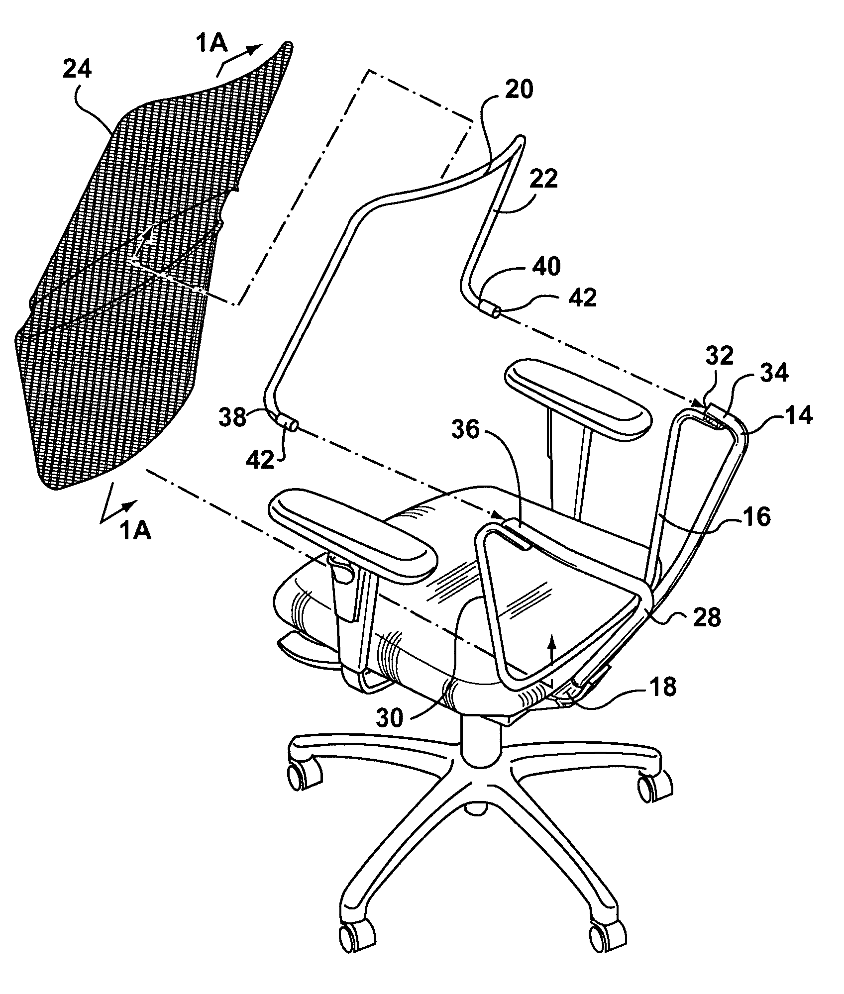
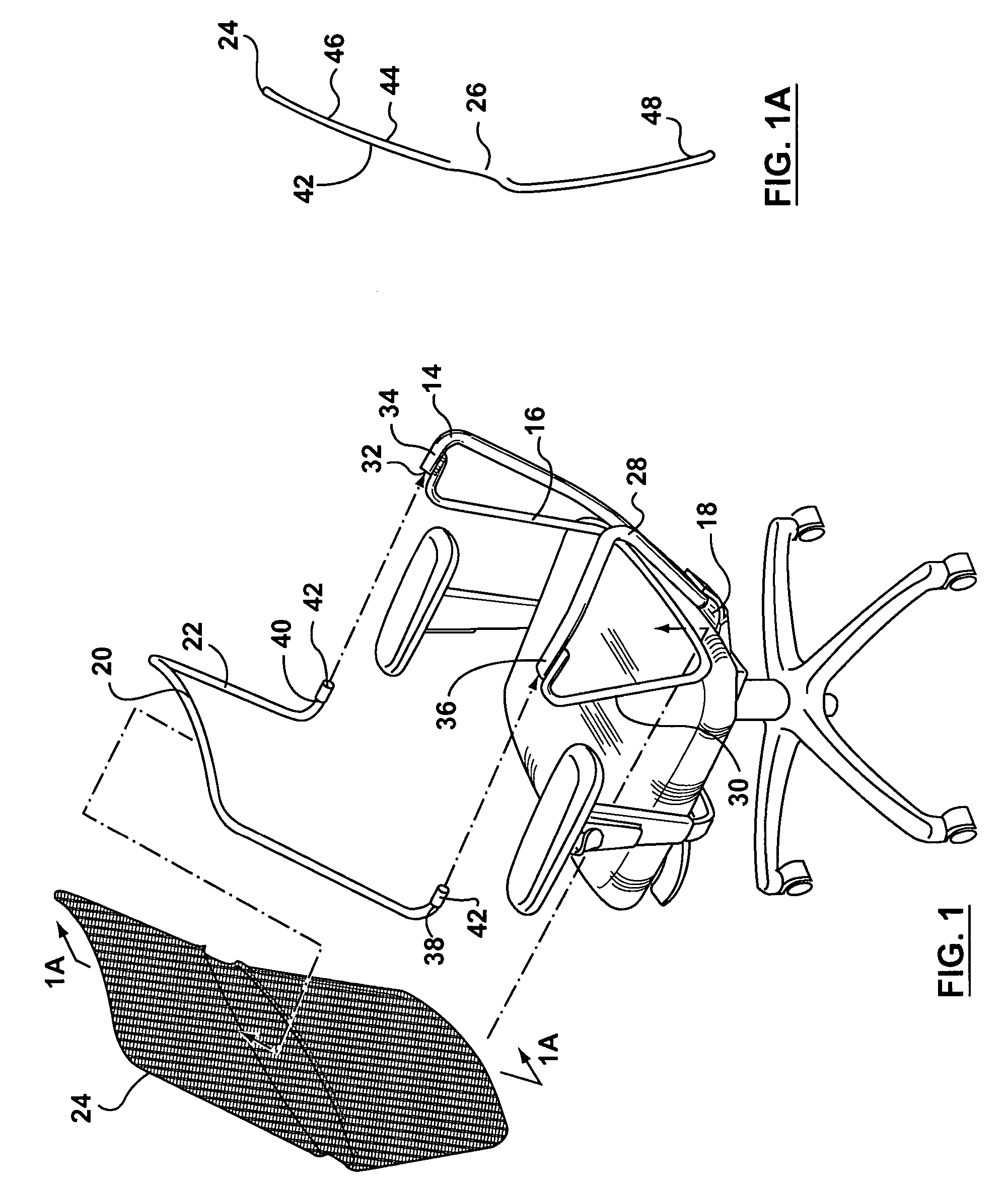
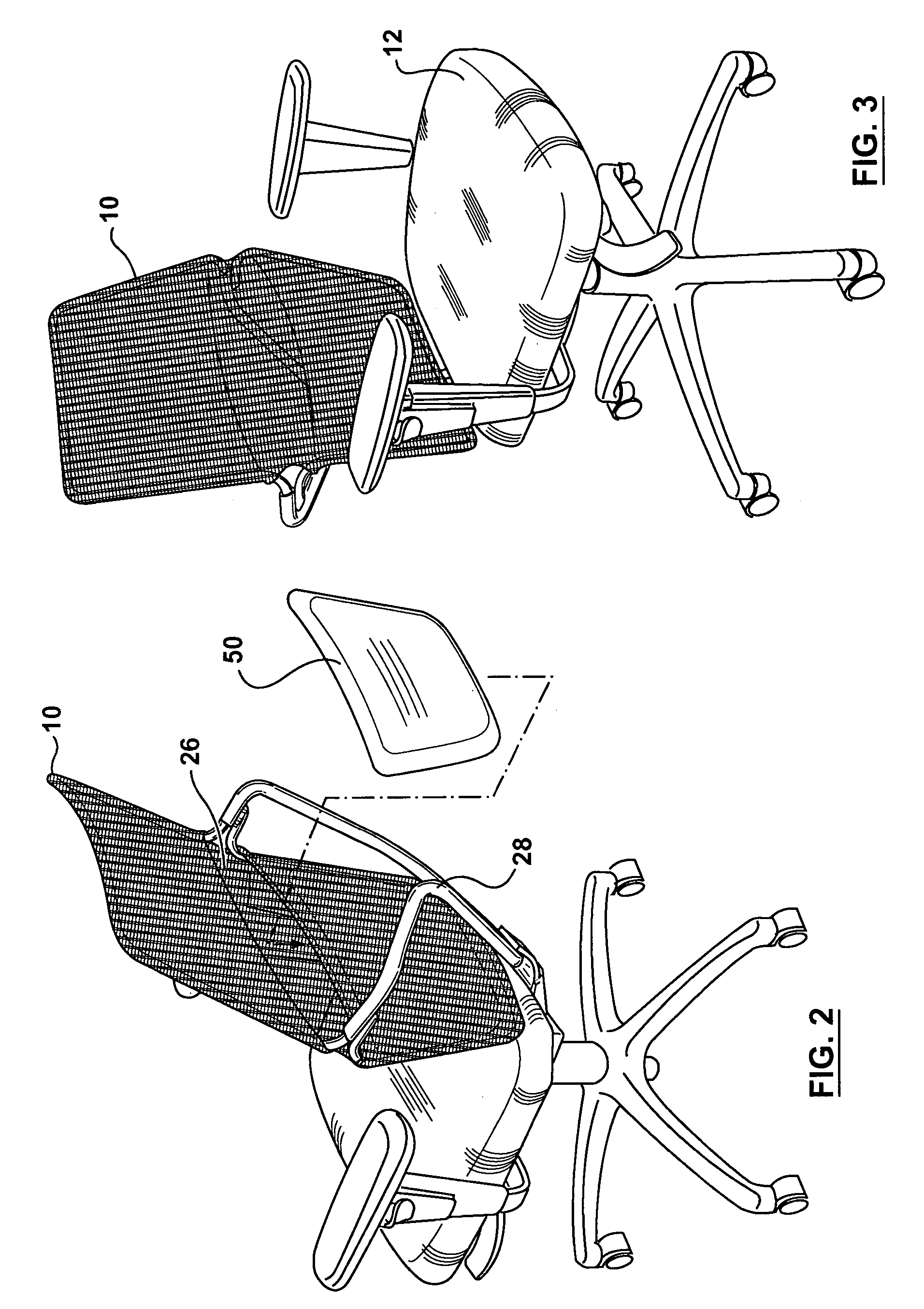
[0024]Referring to FIGS. 1, and 3 there is illustrated in perspective views, a chair back 10 for a chair 12 in accordance with a preferred embodiment of the present invention. The chair back 10 for a chair 12 includes a support frame portion 14 having a defined shape 16 and is adapted to attach to a chair base member 18. The chair back 10 for the chair 12 may also include a tensioning frame portion 20 having a defined shape 22 and a removable elastomeric pocket or support sleeve 24 having an opening 26 adapted to receive the defined shape 16 of the support frame portion 16 and the defined shape 22 of the tensioning frame portion 20.

[0025]Referring to FIGS. 1 and 6 the support frame portion 14 may be further defined to include a Y-shaped portion 28 that attaches the support frame portion 14 to the chair base member 18, and a support member 30 that is mounted to the Y-shaped portion 28. The support member 30 engages the removable elatomeric support sleeve 24 when the chair back 10 is ...


PUM


Abstract

A chair back for a chair that includes a support frame portion having a defined shape and is adapted to attach to a chair base member. The chair back for a chair may also include a tensioning frame portion having a defined shape and a removable elastomeric support sleeve having an opening adapted to receive the defined shape of the support frame portion and the defined shape of the tensioning frame portion. The removable elastomeric support sleeve may be slid first over the support frame portion so as to conform the removable elastomeric support sleeve to the defined shape of the support frame portion. The removable elastomeric support sleeve may then be slid second over the tensioning frame portion thereby conforming the elastomeric support sleeve to the defined shape of the tensioning frame portion. The support frame portion may be adapted to receive and secure the tensioning frame portion, so that the force of connecting the tensioning portion to the support frame portion locks the defined shape of the support frame portion and the defined shape of the tensioning frame portion to one another along with the removable elastomeric support sleeve and therefore forms the chair back.

Description

FIELD OF THE INVENTION[0001]This invention relates in general to chair backs and more particularly to a chair back for a chair having a frame and a removable mesh knitted sock or sleeve that can accommodate different shaped backs and is held in place on the chair frame via the tension within the knitted sock and the structure of the chair frame therefore not requiring fasteners.BACKGROUND OF THE INVENTION[0002]Chair backs have traditionally included components such as wood or metal supports, some form of padded composite, and upholstery, so as to form a chair back that then provides support as well as a pleasing look. Typically a chair back has included a support frame that can be a rigid panel, followed by padding or stuffing that is then covered by fabric. The fabric can be positioned and secured a number of ways to support the frame. The support frame defines the shape of the chair back and can be a wide variety of shapes. The shape of the chair back however has to be sufficient ...

Claims


Application Information

Patent Timeline
Patent Type & Authority Patents(United States)
IPC IPC(8): A47C31/00A47C7/02A47C7/28A47C7/44
CPCA47C7/40A47C31/02
Inventor HARLEY, ALEXANDER PETRIE
Owner ALLSEATING CORPORAITON
Learn More