
Eyeglasses with a clock or other electrical component

Active Publication Date: 2006-01-05
INGENIOSPEC
View PDF52 Cites 110 Cited by
  • Summary
  • Abstract
  • Description
  • Claims
  • Application Information

AI Technical Summary

Benefits of technology

[0009] In one embodiment, the present invention relates to having a clock at least partially embedded in a pair of glasses. With the clock at least partially embedded in the glasses, the wearer does not need to carry a separate watch in order to know what time it is. For example, the clock can be in one of the temples of the glasses at a region close to the hinge of that temple, with the clock facing the wearer. With the clock in that position, the wearer may be able to see the time or the time may be visible to the wearer, without the need to take the glasses off. In an alternative example, the clock, which can be a digital clock, can be in a temple arrangement of a pair of glass

Problems solved by technology

Some people are already burdened by carrying too many separate devices and it can be expensive and inconvenient when a device is lost or forgotten.
Some of these glasses can be quite expensive, particularly those with a famous brand name.
After-market enhancements or modifications to a pair of glasses are not readily available.

Method used


Image

  • Eyeglasses with a clock or other electrical component
  • Eyeglasses with a clock or other electrical component
  • Eyeglasses with a clock or other electrical component

Examples


Embodiment Construction

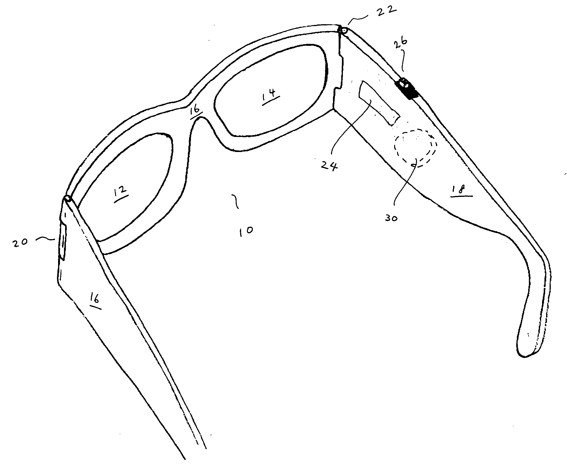
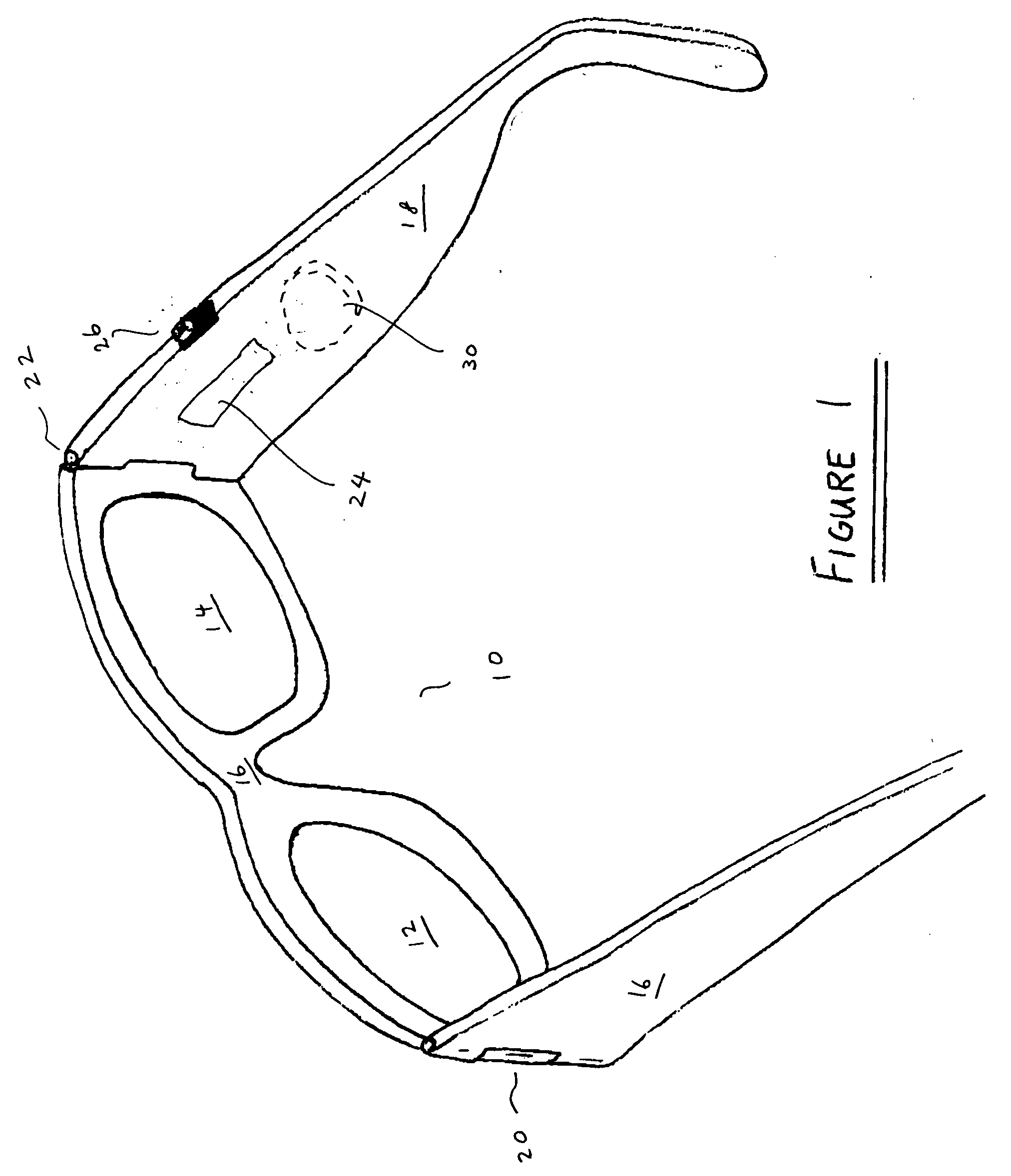
[0016]FIG. 1 shows a pair of glasses according to one embodiment of the present invention. The pair of glasses 10 has a first lens holder 12 and a second lens holder 14. Both lens holders 12, 14 are for receiving lenses. The first lens holder 12 has a first side and a second side. The second lens holder 14 also has a first side and a second side. The pair of glasses has a bridge element 16. The bridge element 16 is coupled to the first side of the first lens holder 12 and the second side of the second lens holder 14. In one embodiment, the lens holders and the bridge element 16 are not separate pieces, but are an integral piece.

[0017] The pair of glasses 10 also includes a first temple 16 and a second temple 18. The first temple 16 is pivotally secured to the second side of the first lens holder 12 through a joint or hinge 20. The second temple 18 is pivotally secured to the first side of the second lens holder 14 through another joint or hinge 22.

[0018] The glasses 10 shown in FI...


PUM


Abstract

A pair of glasses includes a clock that is at least partially embedded in the glasses. The clock can be in one of the temples of the glasses. In one implementation, the clock can be positioned at a region close to a hinge of the corresponding temple, with the clock facing inward towards the user. The clock can also be in a temple arrangement. Instead of or in addition to a clock, other types of electrical components can be at least partially embedded into a pair of glasses or a temple arrangement of a pair of glasses. For example, the other electrical components can pertain to a RFID tag, a temperature sensor or an eyewear finder.

Description

CROSS-REFERENCE TO RELATED APPLICATIONS [0001] This application is a continuation-in-part of U.S. patent application Ser. No. 10 / 964,011, filed Oct. 12, 2004, and entitled “TETHERED ELECTRICAL COMPONENTS FOR EYEGLASSES,” which is hereby incorporated herein by reference, which in turn claims priority to each of: (i) U.S. Provisional Patent Application No. 60 / 509,631, filed Oct. 9, 2003, and entitled “TETHERED ELECTRICAL COMPONENTS FOR EYEGLASSES,” which is hereby incorporated herein by reference; (ii) U.S. Provisional Patent Application No. 60 / 527,565, filed Dec. 8, 2003, and entitled “ADAPTABLE COMMUNICATION TECHNIQUES FOR ELECTRONIC DEVICES,” which is hereby incorporated herein by reference; (iii) U.S. Provisional Patent Application No. 60 / 562,798, filed Apr. 15, 2004, entitled “EYEWEAR WITH ULTRAVIOLET DETECTION SYSTEM,” and which is hereby incorporated herein by reference; (iv) U.S. Provisional Patent Application No. 60 / 583,169, filed Jun. 26,2004, entitled “ELECTRICAL COMPONENTS...

Claims


Application Information

Patent Timeline
IPC IPC(8): G02C5/00G02C1/00G02C5/14G02C7/10G02C11/00G02C11/06
CPCG02C5/001G02C11/10G02C11/06
Inventor HOWELL, THOMAS A.CHAO, DAVIDTHOMAS, C. DOUGLASSTONG, PETER P.
Owner INGENIOSPEC
Features
  • Generate Ideas
  • Intellectual Property
  • Life Sciences
  • Materials
  • Tech Scout
  • Unparalleled Data Quality
  • Higher Quality Content
  • 60% Fewer Hallucinations
Learn More