
Hand driving cycle exerciser
a technology of hand-driven cycle and exerciser, which is applied in the direction of gymnastic exercise, sport apparatus, cycles, etc., can solve the problems of cycle exerciser instability and cycle exerciser instability
- Summary
- Abstract
- Description
- Claims
- Application Information
AI Technical Summary
Problems solved by technology
Method used
Image

Examples
Embodiment Construction
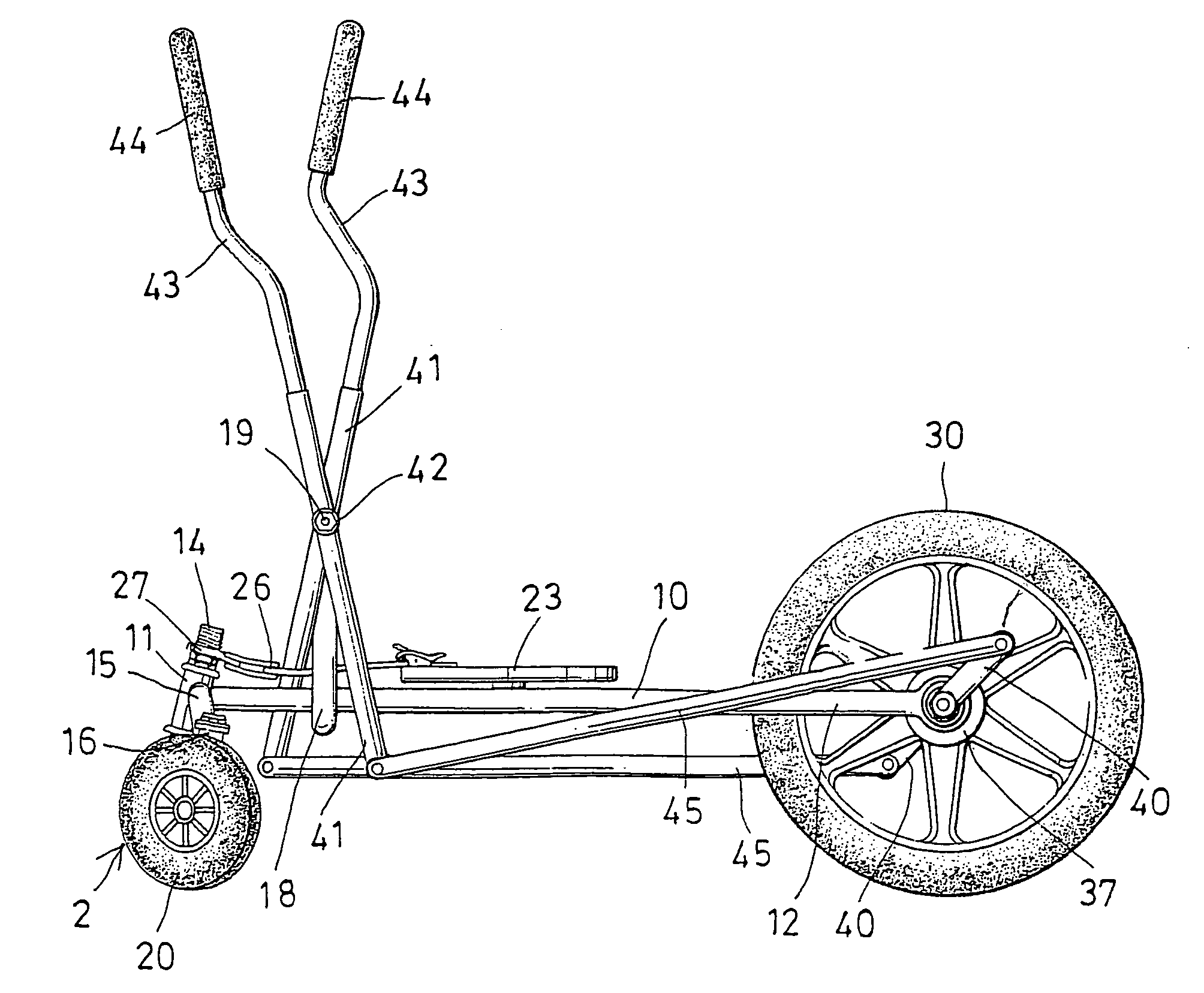
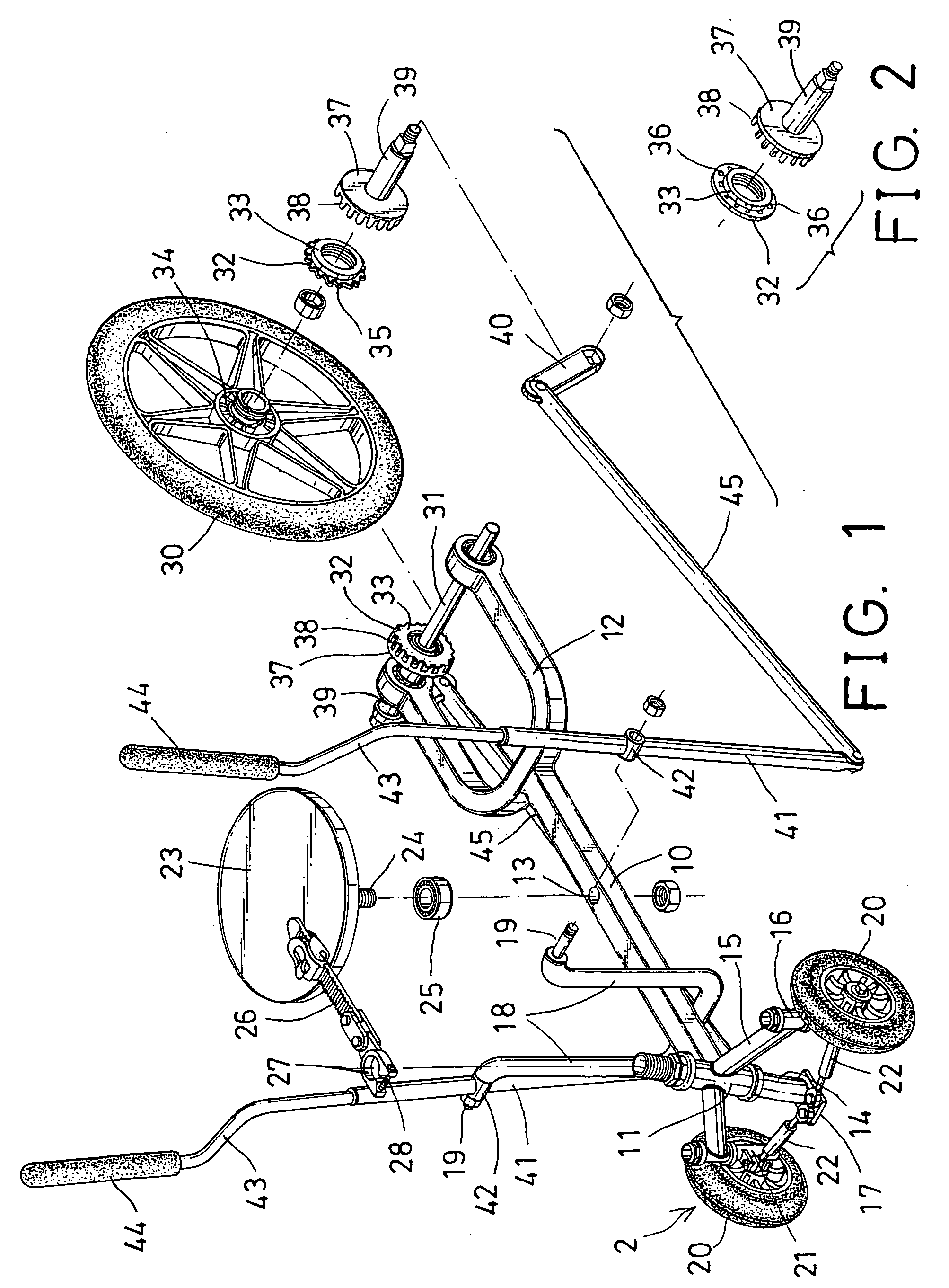
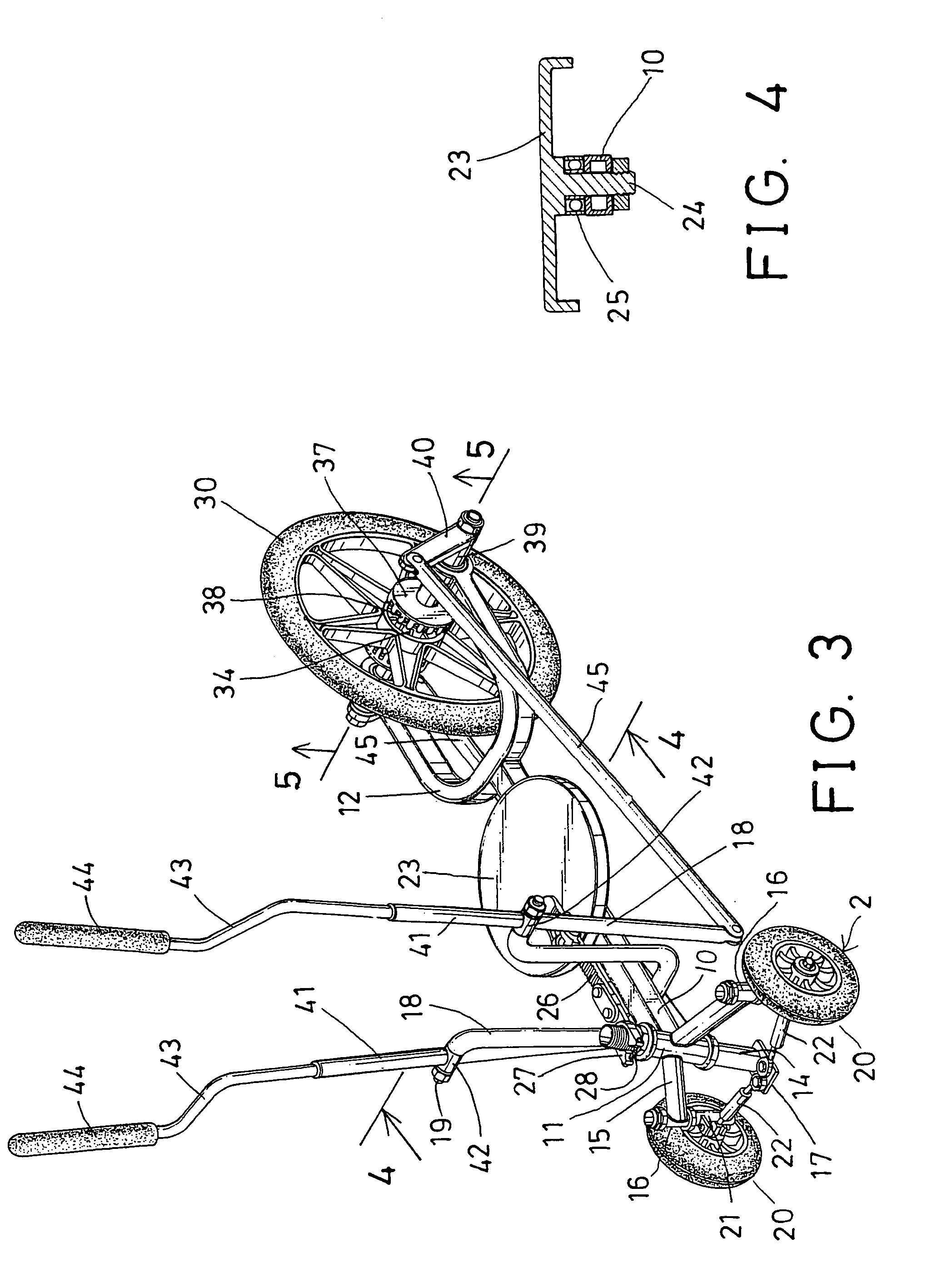
[0028] Referring to the drawings, and initially to FIGS. 1-6, a hand driving cycle exerciser in accordance with the present invention comprises a base 10 including a front tube 11 secured to the front portion thereof and extended vertically, and including a fork 12 secured to the rear portion thereof, and including a hole 13 formed in the middle portion thereof.
[0029] A shaft 14 is rotatably secured in the front tube 11 of the base 10. The front tube 11 includes two arms 15 laterally and / or forwardly extended therefrom, and each having a barrel 16 secured thereto and extended vertically. A bar 17 is secured to the bottom of the shaft 14 and extended forwardly from or beyond the shaft 14. The base 10 further includes a pair of posts 18 extended upwardly therefrom, and each having a pin 19 laterally extended therefrom.
[0030] A front wheel device 2 includes one or more, such as two front wheels 20 rotatably attached to the barrels 16 of the front tube 11 with pivot rods 21 respective...
PUM
 Abstract
Description
Claims
Application Information