Method and apparatus for measuring the thickness of compressed objects

Inactive Publication Date: 2006-02-16
SUNNYBROOK & WOMENS COLLEGE HEALTH SCI CENT
View PDF8 Cites 5 Cited by
  • Summary
  • Abstract
  • Description
  • Claims
  • Application Information

AI Technical Summary

Benefits of technology

[0007] An object of an aspect of the present invention is to provide an improved method of determining a degree of deflection in a breast compression plate.

Problems solved by technology

However, this method requires that all the markers be shown in the image, and does not measure the flexing of plastic plates.

Method used


Image

  • Method and apparatus for measuring the thickness of compressed objects
  • Method and apparatus for measuring the thickness of compressed objects
  • Method and apparatus for measuring the thickness of compressed objects

Examples


Embodiment Construction

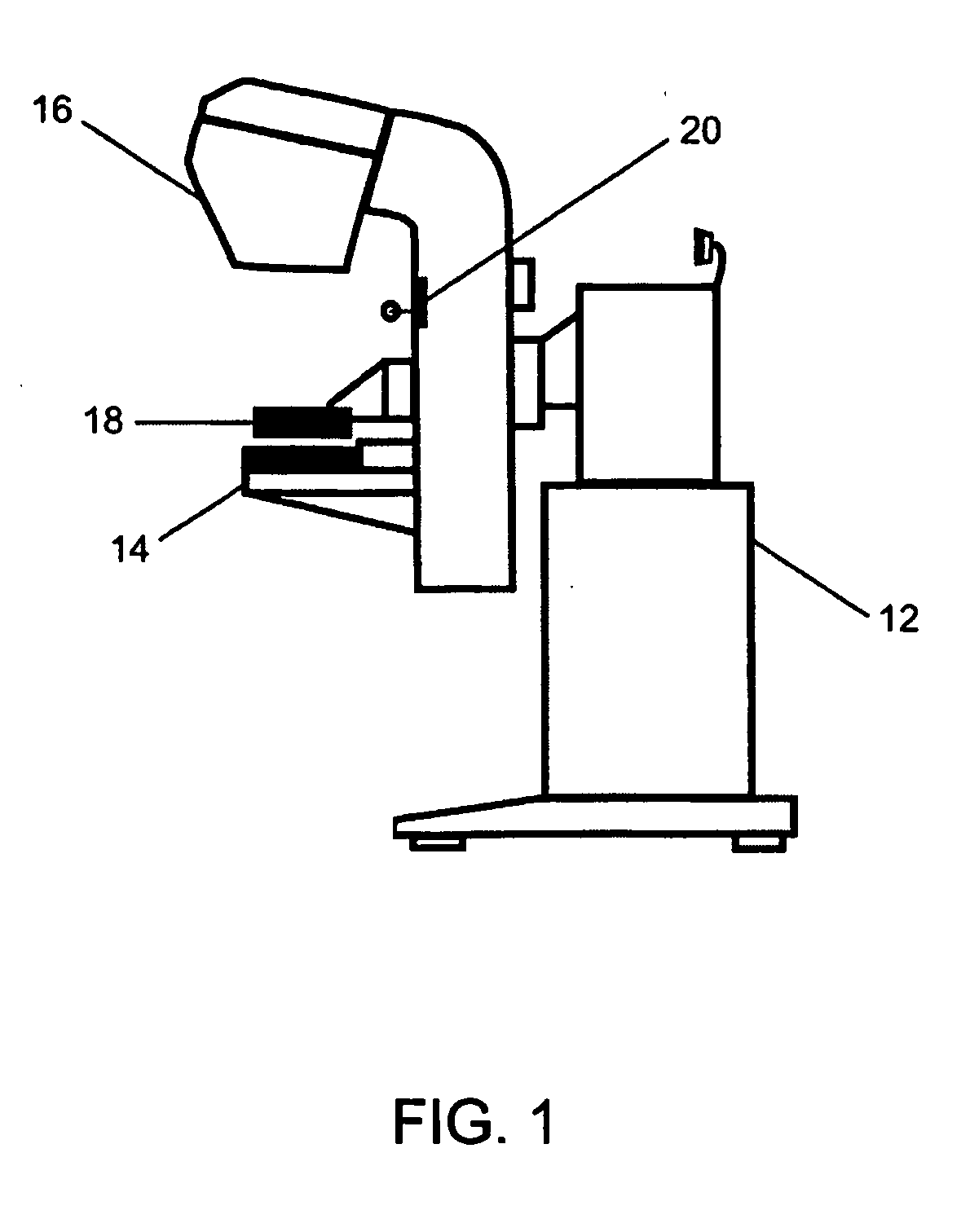
[0017] Referring to FIG. 1, there is illustrated in a perspective view, a mammography machine 12. The mammography machine 12 includes a breast support plate 14, a breast compression plate 18, an x-ray tube 16 and a camera 20. In operation, the x-ray tube 16 projects x-rays through the breast compression plate 18, which is transparent to light and x-rays, through the breast, and through the breast support plate 14. The breast compression plate 18 may be vertically adjusted to accommodate breasts of different dimensions. The breast support plate 14 includes a detector (not shown) that is sensitive to the x-rays. Variation in the density of the breast will have an effect on the x-rays traveling through the breast, which will affect the image left on the detector in the breast support plate 14. These signal variations may then be examined for possible tumors or other conditions. As discussed above, the transmitted x-ray intensity through the breast depends both on the composition of the...


PUM


Abstract

A method and apparatus for determining a degree of deflection in a breast compression plate. The mammography apparatus further includes an optical measuring device. The method and apparatus involve (a) providing a pattern on the breast compression plate, the pattern being imagable by the optical measuring device, and having a plurality of local pattern indicia; (b) adjusting the breast compression plate to a selected height; (c) imaging the breast compression plate using the optical measuring device to provide an image of the pattern, the image having a plurality of local image indicia including an associated local image indicia for each local pattern indicia in the plurality of local pattern indicia; and (d) for each local pattern indicia in the plurality of local pattern indicia, determining an associated local deflection of the breast compression plate from the associated local image indicia.

Description

FIELD OF THE INVENTION [0001] This invention relates in general to a method and apparatus for measuring the thickness of compressed objects, and more specifically relates to a method and apparatus for determining the degree of deflection of a breast compression plate in a mammography apparatus. BACKGROUND OF THE INVENTION [0002] In conventional mammography, a woman places her breast on a breast support plate. A detector is typically mounted under the breast support plate. This detector is sensitive to x-rays. A breast compressor plate that is transparent to light and x-rays presses against the top of the breast to flatten it and to prevent any movement during the mammography process. An x-ray source is then turned on to image the breast, which is between the breast support plate and the breast compression plate. [0003] The transmitted x-ray intensity through the breast is dependent on both the composition of the breast and its local thickness. Most current mammography machines have ...

Claims


Application Information

Patent Timeline
Patent Type & Authority Applications(United States)
IPC IPC(8): A61B6/04A61B5/107
CPCA61B5/1075A61B5/4312A61B6/544A61B6/502A61B6/0414
Inventor YANG, JIWEIMAWDSLEY, GORDONYAFFE, MARTIN
Owner SUNNYBROOK & WOMENS COLLEGE HEALTH SCI CENT
Why Eureka
Try Eureka