Facet device and method

a facet and spine technology, applied in the field of spine devices, can solve the problems of degeneration of discs, pain or other manifestations, nerve or spinal cord damage, structural instabilities, etc., and achieve the effects of less surrounding tissue damage or disruption, reducing discomfort and or deformity, and reducing pain and or deformity

Inactive Publication Date: 2006-02-16
K2M +1
View PDF5 Cites 623 Cited by
  • Summary
  • Abstract
  • Description
  • Claims
  • Application Information

AI Technical Summary

Benefits of technology

[0018] One aspect of the present invention is directed to providing a device and method for alleviating discomfort and or deformity associated with the spinal column. Another aspect of the present invention is directed to providing a minimally invasive implant and method for alleviating discomfort associated with the spinal column. Another aspect of the present invention provides an anchoring device and method that requires less surrounding tissue damage or disruption. Another aspect of the present invention provides reinforcement of the spinous process for use in various spinal systems. Another aspect of the invention provides a minimally invasive, non-invasive, or remote adjustment or lengthening of an orthopedic device. Another aspect of the invention provides a minimally invasive, non-invasive, or remote adjustment, lengthening or shortening of a stabilization device. Another aspect of the present invention also provides an implant system and device suitable for minimally invasive, minimally disruptive and / or percutaneous posterior deployment across a plurality of motion segments and more than two motion segments. Different aspects of the invention may provide distraction forces to relieve pressure on certain structures, compression forces to fix (“fix” as set for the herein shall mean to fix either directly or indirectly and may include dynamic elements) or stabilize motion across structures, shock absorbing qualities to help relieve load from certain structures, and therapeutic activity to reduce inflammation and pain. Other aspects of the invention may supplement or bear load for degenerated, painful, or surgically removed joints, e.g., the facet joint. Another aspect of the invention may provide a method and system for treating deformities such as scoliosis. Other aspects of the invention may include sensors associated with implants or implanted at or near the bones, soft tissue, or joints of the spine and may provide feedback regarding the joint on an ongoing basis. The sensors may also be part of a feedback system that alters a property of an implant in response to sensing information. Another aspect of the invention may provide a device or method for delivering therapeutic substances at or near the spine.

Problems solved by technology

Certain spine conditions, defects, deformities (e.g., scoliosis) as well as injuries may lead to structural instabilities, nerve or spinal cord damage, pain or other manifestations.
For example, back pain is frequently caused by repetitive and / or high stress loads on or increased motion around certain boney or soft tissue structures.
The natural course of aging leads to degeneration of the disc, loss of disc height, and instability of the spine among other structural manifestations at or around the spine.
The facet joints may develop pain due to arthritic changes caused by increased loads.
Furthermore, osteophytes in the neural foramina and thickening of spinal ligaments can lead to spinal stenosis, or impingement of nerve roots in the spinal canal or neural foramina.
However, these implants do not directly address the forces borne by the facet joints.
Disc height loss from degenerative disc disease and aging leads to increased load on the facet joints, which can lead to arthritic, painful, degenerative changes.
In addition to the degeneration of discs causing the narrowing of the foramen, there is also calcification around the foramen causing further narrowing or stenosis resulting in pain to the patient.
However, this type of distraction of adjacent spinous processes is suboptimal for several reasons: The resulting kyphosis is non-physiologic, leading to increased load on the anterior portion of the disc and the vertebral bodies.
This can increase the risk of disc degeneration and vertebral compression fracture.
The spinous processes may fracture due to the distraction forces of the wedge implant.
The amount of distraction is not adjustable to the specific amount of stenosis, and cannot be easily readjusted months to years after the device has been implanted.
The typical techniques for fusion, decompression, and dynamic stabilization require open surgical procedures with removal of stabilizing muscles from the spinal column, leading to pain, blood loss, and prolonged recovery periods after surgery due in part to the disruption of associated body structures or tissue during the procedures.
The spinous process contains thin walls of cortical bone, and thus, has been considered as not ideal for anchoring spinal implants as they may not support the implants under physiologic loads, or the intermittent high loads seen in traumatic situations.
Fixation has been attempted from spinous process to spinous process with poor results.
A disadvantage of this device is that it is not suitable for attaching to a pedicle screw and the depth and angle during deployment can be very difficult to track or visualize, thus increasing the possibility that the screw would extend into the spinal canal.

Method used


Image

  • Facet device and method
  • Facet device and method
  • Facet device and method

Examples


Embodiment Construction

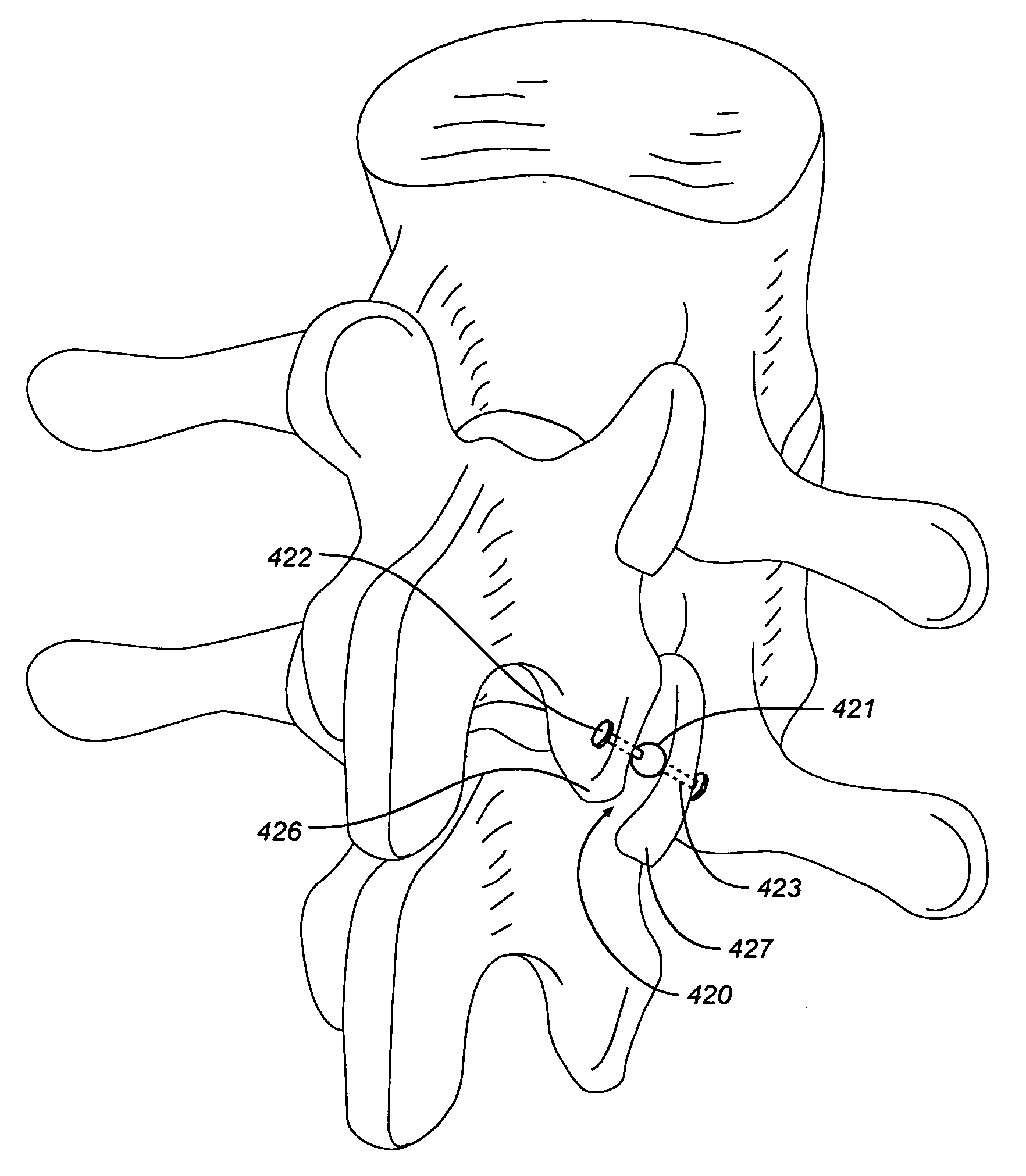
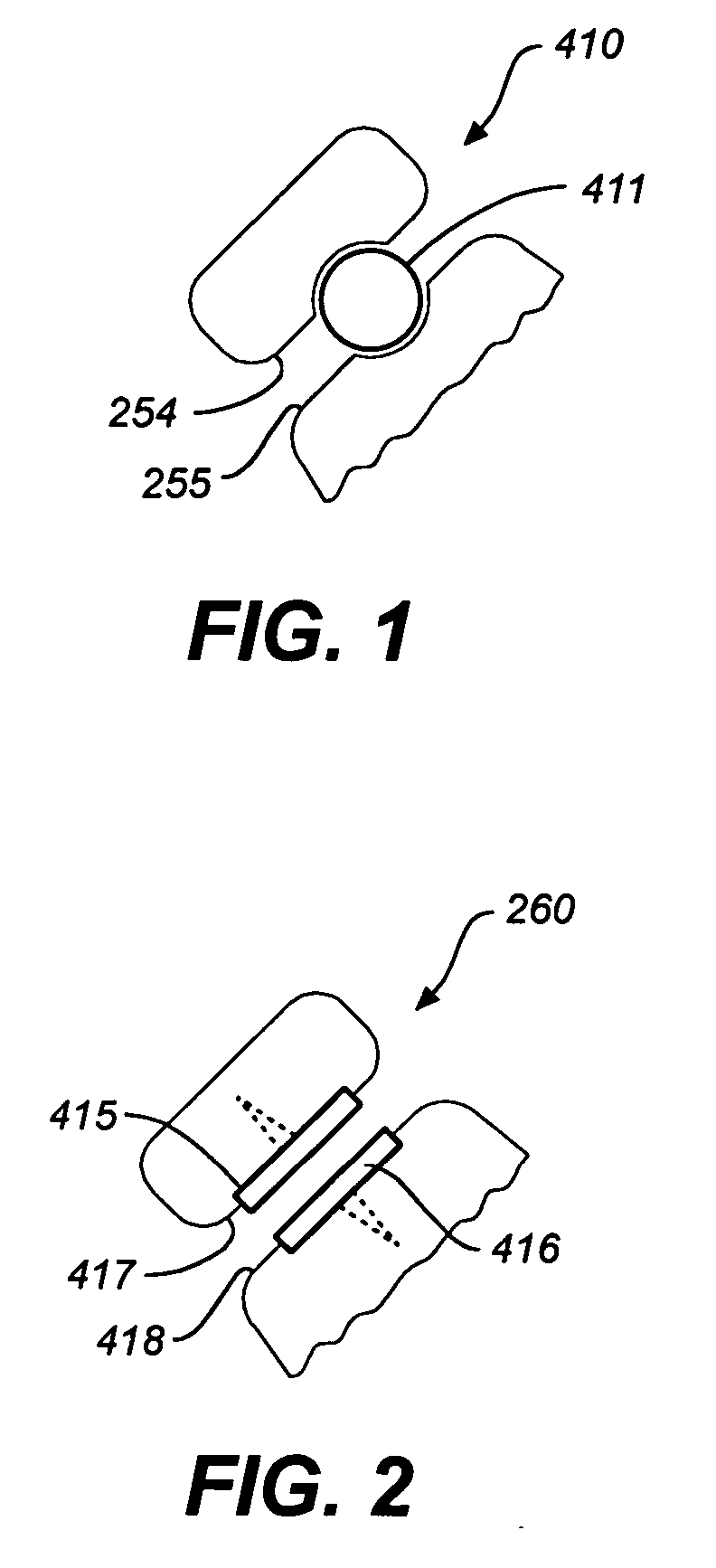
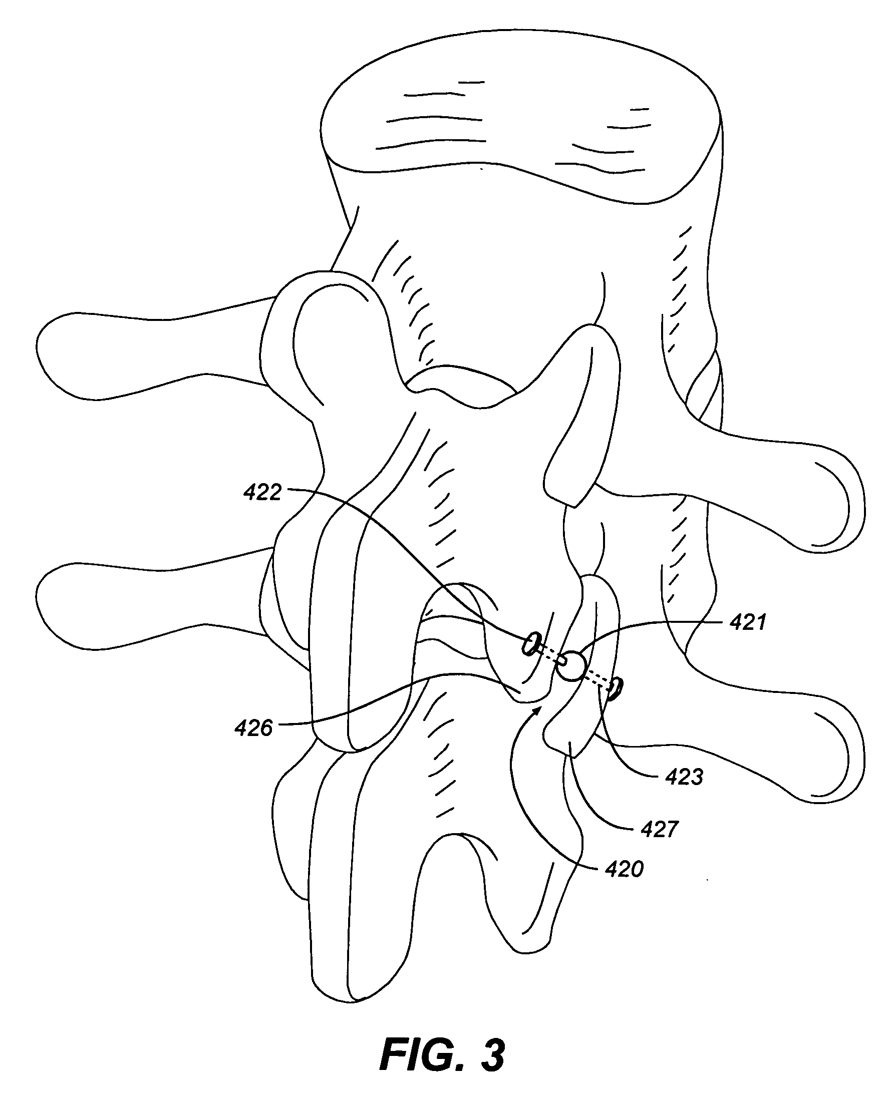
[0072]FIGS. 1-5 illustrate facet repair prostheses in accordance with an embodiment of the invention. Prosthesis 410 comprises a ball bearing 411 implanted between the caudal and the cephalic facets 412, 413 of the zygapopyhseal joint 414. (FIG. 1) The joint 414 is prepared by removing soft tissue between the joints and creating a concavity on adjacent facet plates for receiving the ball bearing.

[0073] In FIG. 2, magnets 415, 416 including smooth interacting bearing surfaces are respectively screwed into the cephalic and caudal facets 417, 418 of the zygapopyhseal joint 419. The magnets 415, 416 are oriented so that like poles face each other (e.g. North-North or South-South) to provide a distraction force at the joint. The magnets may have a center hole through which a rod is inserted to resist the tendency of one magnet to move relative to the other. Each end of the rod may have a diameter larger than the center holes. This system may be used in other joints in the body to mainta...


PUM


Abstract

A spine prosthesis is provided and in particular, related to the facet joint of a spine.

Description

RELATED APPLICATION DATA [0001] The present application claims the priority of Provisional Application No. 60 / 598,882 filed Aug. 3, 2004 and entitled: Spine Treatment Devices and Methods.FIELD OF THE INVENTION [0002] The invention relates to devices to treat the spine, in particular in association with a facet joint, including but not limited to spinal stabilization devices, spinal distraction devices, spinal prostheses, devices to treat pain associated with the spine, and other spinal treatment devices. GENERAL BACKGROUND [0003] Certain spine conditions, defects, deformities (e.g., scoliosis) as well as injuries may lead to structural instabilities, nerve or spinal cord damage, pain or other manifestations. Back pain (e.g., pain associated with the spinal column or mechanical back pain) may be caused by structural defects, by injuries or over the course of time from the aging process. For example, back pain is frequently caused by repetitive and / or high stress loads on or increased...

Claims


Application Information

Patent Timeline
Patent Type & Authority Applications(United States)
IPC IPC(8): A61F2/44
CPCA61B17/7004A61F2310/00179A61B2017/0256A61B2019/464A61F2/4405A61F2/442A61F2002/30079A61F2002/30242A61F2002/30411A61F2002/30507A61F2002/3055A61F2002/30563A61F2002/30566A61F2002/30579A61F2002/30583A61F2002/30601A61F2002/30663A61F2002/30677A61F2002/30874A61F2002/30932A61F2210/0085A61F2210/009A61F2220/0025A61F2230/0071A61F2310/00011A61B17/7064A61B2090/064A61F2002/30873
Inventor CARL, ALAN L.SACHS, DANROSENBERG, MEIR
Owner K2M
Why Eureka
Try Eureka